

An understanding of neuroimaging rests on knowledge of the fundamental principles of:
- neuroanatomy (the structure of the normal brain)
- neuroimaging terminology (how images are described)
- neuroimaging modalities (how images are acquired)
- safety in neuroimaging
1.1 Neuroanatomy
The nervous system is divided into:
- A central nervous system and
- A peripheral nervous system
This book focuses on the central nervous system, which comprises the brain and spinal cord.
The scalp
The scalp is the soft tissue covering the skull vault. A mnemonic for the five layers that make up the scalp, from superficial to deep, is SCALP:
- Skin
- Connective tissue
- Aponeurosis (the galea aponeurotica)
- Loose areolar connective tissue
- Periosteum (pericranium)
The skull
The skull is divided into:
- The neurocranium, i.e. the part encasing the brain, and
- The viscerocranium, i.e. the facial skeleton
The neurocranium


Figure 1.1: Left lateral view of the skull. The neurocranium is shown in blue, and the splanchnocranium in green. The pterion (circled) is the region where the frontal, parietal, temporal and sphenoid bones meet.

The skull vault The skull vault (also called the calvaria) comprises the frontal, parietal (left and right), occipital, temporal (left and right), sphenoid and ethmoid bones (Figure 1.1). In the fully developed skull, these bones are strongly held together 3by fibrous joints called sutures, such as the sagittal, coronal and lambdoid sutures on the superior aspect (Figure 1.2).
The skull base
This anatomically complex structure forms the floor of the cranial cavity. It has many foramina, through which the spinal cord, cranial nerves, blood vessels and other structures pass in or out of the cavity. The largest of the foramina is the foramen magnum.
The skull base is divided into the three cranial fossae: anterior, middle and posterior (Figure 1.3). The small hypophyseal fossa, located in the middle fossa, holds the pituitary gland.


The spine
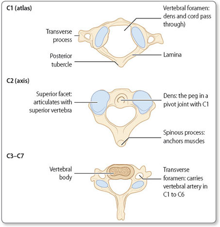
The spine protects the spinal cord. It is a column of individual bones called vertebrae; these differ in structure according to their level but have several key features in common, as shown in Figure 1.4 . From superior to inferior, the vertebrae are (Figure 1.5):
- Seven cervical (C1 to C7)
- Twelve thoracic (T1 to T12)
- Five lumbar (L1 to L5)
- Five sacral (S1 to S5)
- Four coccygeal (Co1 to Co4; these are fused together)
The vertebral bodies are separated by intervertebral discs. Each disc consists of an inner nucleus pulposus and an outer annulus fibrosis.
The cervical spine has several distinct features (Figure 1.6), including:

Figure 1.5: Lateral, ventral and dorsal views of the spine, showing the cervical, thoracic, lumbar, sacral and coccygeal divisions.
- The second cervical vertebra (C2) is called the axis; its odontoid process forms a pivot joint with the atlas to allow rotation of the head
The meninges
The brain is separated from the skull by three membranous layers called the meninges: the dura, arachnoid and pia mater (Figure 1.7). The meninges extend down the spinal canal to encompass the spinal cord, cauda equina and nerve roots. The dura and arachnoid mater terminates at S2, but an extension of the pia mater, the filum terminale, continues to the coccyx.
Dura mater
The dura mater is the thick, outermost layer of the meninges, and itself has an outer (periosteal) and an inner (meningeal) layer. The outer layer of the dura mater is largely adherent to the skull.7

The inner layer deviates deeply at two main locations to form the falx cerebri (within the longitudinal fissure, which separates the right and left cerebral hemispheres) and the tentorium cerebelli (which separates the cerebrum from the cerebellum). The dural venous sinuses are the channels formed between the separation of the two dural layers.
Arachnoid mater
Deep to the dura mater is the arachnoid mater. The arachnoid mater is in contact with the dura mater but separated from the pia mater by the subarachnoid space. Within the subarachnoid space are cerebral arteries, and veins that drain into the dural venous sinuses via bridging veins. Large subarachnoid spaces are termed cisterns.
Pia mater
The cerebrum
The cerebrum is divided into two hemispheres, left and right, separated by the longitudinal (or interhemispheric) fissure. The hemispheres are subdivided into lobes: frontal, temporal, parietal and occipital (Figure 1.8). Each lobe has specific functions (Table 1.1).
Cerebral cortex
The cerebral cortex is the superficial layer of the brain. It has a convoluted structure characterised by gyri and sulci. Two of the most prominent sulci are the central sulcus (or Rolandic fissure), which divides the frontal and parietal lobes, and the lateral sulcus (or Sylvian fissure), which separates the frontal and temporal lobes.

Figure 1.8: Lobes of the brain. The postcentral gyrus (somatosensory region) is part of the parietal lobe. The precentral gyrus (primary motor cortex) is part of the frontal lobe.
The cortex is made up of grey matter, which consists of neuronal cell bodies.
Subcortical structures
White matter is located within the inner part of the cerebrum. It is composed of neuronal axons surrounded by myelin (accounting for the white appearance). Arranged in bundles, these axons form tracts connecting regions of the brain and spinal cord. The corpus callosum is a large white matter tract that connects the two hemispheres of the cerebrum.
Other important subcortical structures include (Figure 1.9):
The basal ganglia This is a group of interconnected subcortical nuclei including the subthalamic nucleus, putamen, caudate nucleus and globus pallidus. They act as a circuit to help fine-tune voluntary movements.10

11The internal capsule This is a pathway for the white matter tracts ascending to or descending from the cerebral cortex.
The thalamus The thalamus relays motor and sensory information to and from the cerebral cortex. It also has a key role in the regulation of consciousness.
The hypothalamus This is located inferior to the thalamus and superior to the pituitary gland. Its functions include mediation of emotional responses and maintenance of homeostasis (e.g. body temperature and blood pressure). The hypothalamus influences the autonomic nervous system and the release of hormones from the pituitary gland.
The pituitary gland
Connected to the hypothalamus by the stalk-like infundibulum, the pituitary gland lies inferior to the optic chiasm (the point at which fibres from the left and right optic nerves cross) (Figure 1.10), and sits within the hypophyseal fossa in the middle cranial fossa. It is divided into an anterior and a posterior lobe. As the so-called ‘master gland’, it controls the secretion of hormones from other endocrine glands.

The cerebellum
The cerebellum lies in the posterior fossa. It is connected to the brainstem by the superior, middle and inferior cerebellar peduncles.
It has a complex array of folds, called folia, and is divided into the following (Figure 1.11):
- The left and right hemispheres, divided by the midline vermis
- The anterior and posterior lobes, divided by the primary fissure
The cerebellum coordinates movement.
The brainstem
The brainstem is divided into three structures (Figure 1.12). From superior to inferior, these are the:
- Midbrain
- Pons
- Medulla
The brainstem is responsible for regulation several vital functions, including:
- the respiratory and cardiovascular systems
- the sleep–wake cycle
- arousal and consciousness
- bowel and bladder control
- nausea and vomiting
- pain
It is also where the nuclei of the cranial nerves (III to XII) are located. Running through the brainstem are white matter tracts made up of the axons of motor and sensory pathways, which enable communication between the brain and the spinal cord.13


The spinal cord
The spinal cord is contained within the spinal canal, the space formed by the vertebral foramina of successive vertebrae. It extends from the brainstem via the foramen magnum in the skull base, to the conus medullaris at about the level of L1 (normal range, T12 to L2). From the conus medullaris, the lumbar and sacral nerve roots descend unbound; the extending nerve roots are known collectively as the cauda equina.

15The spinal cord gives rise to 31 pairs of spinal nerves. The cervical spine has seven vertebrae and the cord has eight cervical spinal nerves:
- each pair of the C1–C7 nerve roots emerges above the numerically corresponding vertebra, and
- the pair of C8 nerve roots emerges below the C7 vertebra
All subsequent nerve roots arise below their corresponding vertebrae.
The spinal tracts
The spinal cord contains white matter tracts that transmit information either from the brain to the peripheral nerves or vice versa (Figure 1.13).
Motor information is transmitted via descending pathways, and sensory information via ascending pathways.
The corticospinal tract This is the pathway of neurones descending from the cortex to synapse with the lower motor neurones. They control voluntary muscle action.
The dorsal (posterior) column This pathway of neurones connects sensory nerve endings to the somatosensory region of the cerebral cortex. It is responsible for conscious proprioception and the sensation of vibration and discriminative touch.
The spinothalamic tract This is the neuronal pathway connecting sensory nerve endings to the somatosensory region of the cerebral cortex. It is responsible for the sensation of crude touch, pain and temperature.
The spinocerebellar tract This pathway of neurones connects sensory nerve endings to the cerebellum. It confers unconscious proprioception.16

Figure 1.14: The circle of Willis. Key to labels: ① Anterior communicating artery ② Pontine arteries ③ Basilar artery ④ Anterior spinal artery ⑤ Second part (A2) of anterior cerebral artery ⑥ First part (A1) of anterior cerebral artery ⑦ Middle cerebral artery ⑧ Posterior communicating artery ⑨ Posterior cerebral artery ⑩ Superior cerebellar artery ⑪ Labyrinthine artery ⑫ Anterior inferior cerebellar artery ⑬ Vertebral artery ⑭ Posterior inferior cerebellar artery.

The arterial system
Arterial supply to the brain is divided into the anterior circulation and the posterior circulation. The internal carotid and vertebral arteries meet to form an anastomotic structure named the Circle of Willis (Figure 1.14), which enables some compensation between the two circulations.
Anterior circulation
The anterior circulation is supplied by the internal carotid arteries. It is the primary supply to the anterior and middle cerebral arteries. The anterior cerebral artery supplies the anteromedial side of the brain (Figure 1.15). The middle cerebral artery supplies the lateral side of the brain. The middle cerebral artery gives rise to the lenticulostriate arteries, which supply subcortical structures of the brain (e.g. the basal ganglia).
Posterior circulation
The posterior circulation is supplied by the vertebral arteries. It is the primary supply to the posterior cerebral arteries and the arteries that supply the cerebellum and brainstem. The posterior cerebral arteries supply the base of the cerebrum and the occipital lobes.18

The venous system
Cortical veins drain into the dural venous sinuses. The largest sinus is the superior sagittal sinus. Where the major sinuses merge (the confluence of sinuses), the venous blood drains into the left and right transverse sinuses and the left and right sigmoid sinuses, and then the left and right internal jugular veins, respectively (Figure 1.16).
The ventricular system
The ventricular system is a collection of four connected compartments filled with cerebrospinal fluid (Figure 1.17). The fluid is produced by the specialised tissue of the choroid plexuses, primarily in the lateral ventricles. It flows from the left and right lateral ventricles, via the interventricular foramina (foramina of Munro), to the third ventricle. It then passes through the cerebral aqueduct (aqueduct of Sylvius) to the fourth ventricle. From the fourth ventricle, the fluid either flows into the subarachnoid space, via the median and lateral apertures (foramina of Magendie and Luschka, respectively), before being absorbed by arachnoid granulations into the bloodstream, or flows down through the spinal subarachnoid space or central canal.19

1.2 Radiological terminology
An understanding of the principles of orientation, views and sections is essential to the interpretation of imaging studies. The terms that describe these principles form the language of radiology.
Orientation
The terms used in radiology generally follow those used in anatomy (Figure 1.18).

- Inferior is used to describe a structure that is lower in position, or situated nearer the soles of the feet, relative to another structure
- Anterior refers to a structure that is in front of another
- Posterior refers to a structure that is behind another
- Medial refers to a structure that is closer to the midline of the body relative to another
- Lateral refers to a structure that is further away from the midline of the body relative to another
- Ipsilateral means on the same side of the body relative to another structure
- Contralateral means on the opposite side of the body relative to another structure
These terms are all used consistently in descriptions of features of the brain and spinal cord. In contrast, the terms rostral, caudal, dorsal and ventral have different meanings when applied to features of these two anatomical sites (Figure 1.18).
Views
Radiographs are produced by transmitting X-rays through the subject. The direction of transmission determines the view obtained (Figure 1.19). An anteroposterior view is produced by transmitting X-rays through the front of the subject towards a detector positioned behind them. A lateral view is produced by transmitting X-rays through the subject from one side (either left or right) towards a detector on the opposite side.
Sections
In modern neuroimaging (computerised tomography, CT, and magnetic resonance imaging, MRI), multiplanar techniques are used to visualise the brain and spinal cord in cross-sections, or ‘slices’ (Figure 1.20).22

- A sagittal section provides an image of the brain or spinal cord in a lateral plane (i.e. from the side), which shows relations between structures in terms of superior versus inferior and anterior versus posterior
- An axial (or transverse) section provides an image of the brain or spinal cord in a horizontal plane, enabling comparison of anterior versus posterior and medial versus lateral structures

Figure 1.20: T1-weighted MRI scan of the head, showing sagittal (a), coronal (b) and axial (c) sections.
1.3 Imaging modalities
A basic understanding of the principles underlying different neuroimaging modalities facilitates interpretation of the images obtained.
Plain radiography
Radiographs are generally easy to acquire (even possible at the bedside), widely available, rapidly acquired, cost effective and have a significantly lower radiation dose than CT. Due to advances in multi-planar neuroimaging, CT and MRI have largely superseded plain radiography in neuroimaging.24
Principles
X-rays from a single-source radiation emitter are directed at the body part of interest, positioned in front of an X-ray detector (film or digital). The X-rays are attenuated (absorbed or scattered) to varying degrees by body tissues of different densities. The resulting variation in X-rays reaching the detector is visualised as differences in contrast in the image captured, i.e. the radiograph.
Applications
In a radiograph, it is not possible to differentiate the skull from the intracranial contents, because X-rays are highly attenuated by the skull. Therefore, radiography is not used for imaging studies of the brain. However, there are specific indications for skull radiographs in clinical practice, for example to visualise the characteristic lytic lesions of multiple myeloma, for ventriculoperitoneal shunt series, and for skeletal surveys in non-accidental injury in children.
Plain radiographs are routinely used to image the spinal column. Indications include trauma (to investigate for fractures, vertebral alignment and stability), spinal deformities (e.g. scoliosis), degeneration and spinal column tumours. Similarly to skull radiographs, the spinal cord cannot be visualised on spine radiographs due to the high density of the spinal column.
Computerised tomography
The availability and fast image acquisition of CT makes it the imaging modality of choice in neurological emergencies (such as trauma and acute cerebrovascular conditions). The advantages and limitations of CT compared with those of MRI are shown in Table 1.2.
Principles
Computerised tomography images the body in cross-section. This is an advantage over plain radiography, in which the interpretation of images is made difficult by the superimposition of body tissues of different densities.25
|
Beams of X-rays are directed through the patient along multiple linear paths and measured by a series of X-ray detectors (Figure 1.21). Attenuation values for each discrete three-dimensional element of volume (voxel; Figure 1.22) is calculated using data from X-ray paths intersecting at the coordinates of the voxel. Using these values, a three-dimensional density map can be visualised as grey-scale image that we can interpret.
Applications
The introduction of contrast agents into the vascular system significantly increases the density of blood vessels, thereby enabling them to be clearly differentiated from surrounding body tissue. Usually the contrast agent is an iodinated compound because their density is clearly visible on CT, they are soluble and do not harm the body. Contrast is used in CT angiography, CT venography and also to identify dysfunction of the blood–brain barrier (e.g. in the case of contrast-enhancing brain tumours).26

Figure 1.21: CT image acquisition. In plain radiography, a single X-ray beam is transmitted through the patient towards a detector. In CT, the X-ray emitters and detectors rotate around the scanner gantry in order to transmit X-rays in multiple, intersecting paths. Using a method called ‘back-projection’, the attenuation at each voxel is calculated.

Figure 1.22: A pixel (a picture element) is two-dimensional, i.e. is a square. A voxel (a volume element) is three-dimensional, i.e. is a cube or cuboid.
27CT angiography Contrast is used to improve visualisation of the arterial system. In the context of neuroimaging, it is used to identify vascular abnormalities such as aneurysms.
CT venography Contrast is also used to improve visualisation of the venous system. The venous system can be enhanced selectively by increasing the delay between contrast administration and image acquisition. This technique can be used to investigate for dural venous sinus thrombosis.
CT perfusion This measures cerebral blood flow. It is used to determine the amount of salvageable parenchyma (the penumbra) in patients who have had a stroke, and to identify vasospasm in subarachnoid haemorrhage.
Magnetic resonance imaging
Magnetic resonance imaging (MRI) is a powerful neuroimaging modality. It shows both the structures and pathology of the brain and spinal cord in better detail than CT. However, image acquisition is much longer, the scanner is more claustrophobic and patients can be upset by the loud noises that it makes. Table 1.2 compares the advantages and limitations of MRI and CT.
Principles
MRI is based on altering the properties of the abundant hydrogen atoms within the body. This is done by exposing the patient to the strong magnetic field of the large cylindrical magnet that is part of the MRI scanner (Figure 1.23).
Each hydrogen atom contains a single proton nucleus that spins around a central axis. In the magnetic field of the MRI scanner, the central axis of each proton aligns with the direction of the magnetic field. Although aligned, the protons spin out of phase with each other. A radiofrequency pulse is then applied, which causes the central axis of each proton to realign perpendicular to the direction of the magnetic field; consequently, all the protons spin in phase. When the radiofrequency pulse ceases, each proton's central axis realigns with the direction of the magnetic field, and the protons gradually return to spinning out of phase.28

29Variation in both the alignment of the protons and their phase of spin results in different signals for different tissues. This is represented by differences in the greyscale image generated.
Clinical MRI scanners vary in the strength of their magnetic field (for which the unit is the tesla, T); strengths of 1.5 and 3.0 T are typical. The higher the number of teslas, the higher the signal-to-noise ratio.
Applications
Contrast agents are used in MRI to enhance imaging of blood–brain barrier disruption, tumours, inflammation, demyelination and infection. Gadolinium is a commonly used contrast agent used in MRI and works by increasing signal on T1-weighted imaging.
Magnetic resonance angiography and venography These techniques use specific magnetic resonance signals to improve visualisation of the arteries and veins, respectively. Unlike CT angiography and CT venography, they do not necessarily require the use of a contrast agent.
Diffusion-weighted imaging This technique is used to estimate the diffusion of water in tissue. It is used to investigate for cerebral ischaemia, infection, traumatic brain injury and degenerative disease.
Diffusion tensor imaging This is used to study the direction of diffusion within tissues, and can be used to determine the orientation of white matter tracts. In tractography (also called fibre-tracking), data from diffusion tensor imaging are used to generate a three-dimensional map of the white matter tracts. Tractography is increasingly being used for neurosurgical planning and intraoperative guidance.
Functional MRI This is used to measure brain activity. It uses the technique of blood oxygenation level–dependent imaging to show regions of increased blood flow and oxygenation, 30which are assumed to represent regions of increased neuronal activity. As well as being an increasingly useful tool in neuropsychological research, functional MRI is used to prevent iatrogenic injury and subsequent post-surgical neurological deficits in patients undergoing neurosurgery.
MRI spectroscopy This technique is used to measure the chemical composition of tissue. Chemicals measured include N-acetylaspartate, choline, lactate, creatine and glutamate. Spectroscopy is used to investigate and differentiate between brain lesions (e.g. tumours, infarcts and infections).
MRI perfusion This is similar to CT perfusion. It allows the approximate quantification of cerebral blood flow and blood volume. It is particularly useful in the assessment of tumours, for their differentiation from tumour mimics and the identification of aggressive features for targeted biopsy.
1.4 Patient safety
Neuroimaging is not without risk. For each patient, the risks of image acquisition need to be carefully balanced against the clinical usefulness of the images that will be obtained.
Radiography and CT imaging
Both plain radiography and CT use ionising radiation. Radiation causes cellular and genetic damage, and significant exposure increases the risk of developing cancer. Modern equipment minimises the radiation dose but cannot eliminate it. In particular, children are more radiosensitive than adults and the risks versus benefits should be especially carefully considered. The fetus is especially susceptible to irradiation injury. All girls and women of child-bearing age are asked if there is any possibility that they could be pregnant. In pregnancy, clinicians may choose a different imaging modality, deferring non-urgent imaging or carrying out a risk–benefit analysis specific to the patient.31
| |||||||||||||||||||||
The effective dose of radiation to which a patient is exposed is measured in Sieverts (Sv); 1 Sv = 1 J/kg. Example doses are given in Table 1.3, which illustrates the higher dose of CT compared with a radiograph.
MRI safety
The MRI scanner contains a large superconducting magnet, and patients are exposed to its magnetic field. There is no evidence that exposure to high-strength magnetic fields contributes to any pathological processes. However, ferromagnetic objects are made hazardous by their strong attraction to the powerful magnetic field.
32Any external ferromagnetic material that enters the magnetic field is immediately and forcefully propelled towards the bore (centre) of the scanner; this is known as the missile effect. Potential projectiles that could cause injury include oxygen canisters, metal chairs, jewellery, buckles, etc. These must be removed before imaging.
Internal ferromagnetic materials have the potential to be displaced or distorted. Surgical devices, implants (e.g. cochlear implants) and foreign bodies (e.g. metal fragments in the eye). Electronic devices, such as pacemakers, will be damaged. Displacement or dysfunction of these objects will injure or be life-threatening to the patient.
Contrast reactions
All contrast agents have the potential to cause harm. Some may cause contrast-induced nephropathy, therefore the risk and benefits of imaging requiring contrast in patients with renal impairment should be considered carefully. Other risks include immediate or delayed allergic reaction.