


INTRODUCTION TO CORNEAL TOPOGRAPHY
Corneal topography is a noninvasive imaging technique for mapping the anterior surface of the cornea. Taking into account that the cornea is responsible for over two thirds of the total eye's refractive power, its shape is of critical importance in determining the quality of the ocular optical system and therefore the quality of vision. Very small changes in corneal shape resulting from surgery or disease can have a dramatic effect on the focus of the retinal image. For this reason, understanding and quantifying corneal contour has become an essential preoperative measurement for designing surgical intervention in refractive surgery, for assessing the outcomes of keratoplasty, as well as corneal transplantation, or for evaluating the optical performance of the eye. Different methods for measuring corneal topography have been developed along several centuries, depending on the incoming advances of technology.
Different features used to characterize optical properties of the cornea must be introduced in advance:
Height or Elevation
Distance of each point of a surface from a reference surface (Fig. 1.1). Fine details of the cornea can be obtained by taking the sphere as the reference surface.
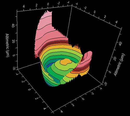
Once the shape of the corneal surface has been expressed in terms of height, other parameters such as slope, curvature and power can be calculated from it.
Radius of Curvature
The radius of curvature is usually expressed in millimeters and it is a way of characterizing the curvature of the anterior surface of the cornea. Corneas with a steep surface slope have a small radius of curvature while those with a flatter surface slope have a larger radius of curvature.4
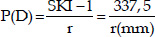
Power
The power is an optical property expressed in diopters (D) that depends on the shape of the surfaces and the variation of refractive index between both sides of the surface. The keratometric diopter is calculated using the radius of curvature and the standard keratometric index of refraction (SKI = 1.3375), an approximation derived from some assumptions. We can express this relation with the following formula:
The evolution of the quantitative assessment of the anterior corneal curvature has been progressive and its range of measurement has been extended from the four points a few millimeters apart measured by keratometers to a grid of thousands of points covering almost the entire cornea measured by computerized corneal topography.
Corneal Shape
The cornea is an optical structure of the eye characterized by its transparency and it is formed by two surfaces. The average anterior and posterior corneal power are + 48.6 D and - 6.8 D respectively.
To simplify this model in clinical practice, we consider only one refractive surface with a resulting corneal power of about 42-44 keratometric diopters.
Normal corneas have some interesting features:
- Viewed from the front, the cornea is slightly oval with vertical and horizontal diameters of approximately 11 and 12 mm respectively.
- It has an average apical radius of curvature of about 7.8 mm, with a normal range of 7-8.5 mm.
- The average corneal keratometry profile changes little with age. It has been stated that the cornea flattens about 0.5 D by the age of 30 years and it steepens about 1 D by the age of 70 years. During adulthood, the horizontal radius is usually 0.05-0.25 mm flatter than the vertical, which contributes to higher incidence of with the rule astigmatism in young adults. This difference between curvatures of vertical and horizontal meridians decreases with age, finally disappearing at the age of 70 years. The higher incidence of against the rule astigmatisms at advanced ages is mainly explained by the lenticular changes.
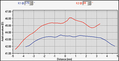
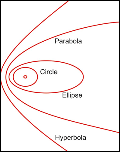
- The normal cornea flattens progressively from the center to the periphery by 2-4 D (Fig. 1.2), with a more pronounced flattening of the nasal area than the temporal area. This gives to the anterior corneal surface an aspherical configuration and it is assumed to have a conic section.5Fig. 1.2: Profile of the steepest and flattest meridian of a cornea (progressive flattening toward the periphery)This model could be represented by means of this equation:where the Z axis is the axis of revolution of the conic, R is the radius at the corneal apex, and Q is the asphericity, a parameter used to specify the type of conicoid. This parameter (Q) can take different values giving the following different kind of configurations (Fig. 1.3):
- Q = 0: Perfect spherical surface
- Q > 0: Oblate surface, ellipsoid with major axis in X-Y plane
- (-1) < Q < 0: Prolate surface, ellipsoid with major axis in Z direction
- Q = -1: Paraboloid configuration
- Q < -1: Hyperboloid configuration

Several studies have checked that the anterior corneal configuration tends to be prolate. This means negative asphericity values, ranging normal values from -0.26 to -0.11, depending on the study considered.
In a map with a color-coded power scale (corneal topographic map), we can see how the dioptric power declines towards the periphery (Fig. 1.4). Depending on how the dioptric power declines, we can recognise five different normal topographic patterns. The approximate distribution of keratographic patterns described in normal eyes includes the following:
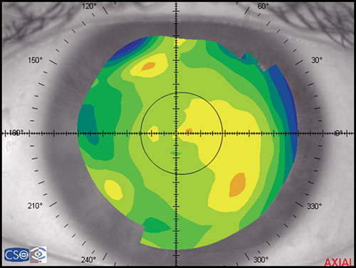
- Round: 23% (Fig. 1.5)
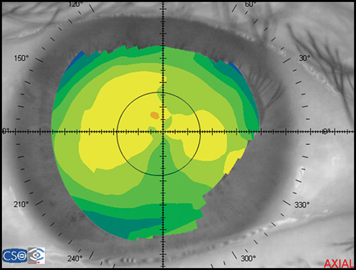
- Oval: 21% (Fig. 1.6)
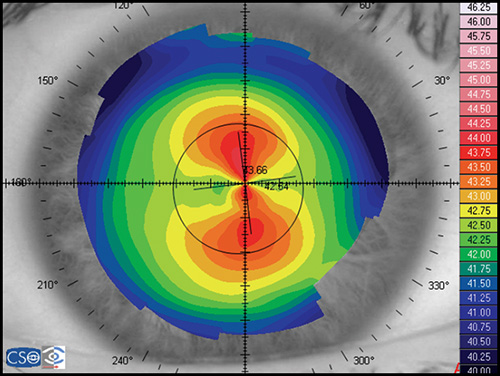
- Symmetric bow tie: 18%
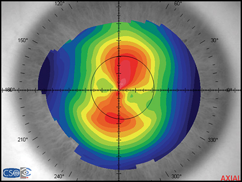
- Asymmetric bow tie: 32% (Fig. 1.7)
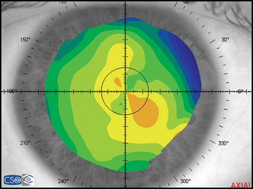
- Irregular: 7% (Fig. 1.8)
The bow tie configuration represents the existence of corneal astigmatism. The localization of the steepest axis defines against-the-rule astigmatism (horizontal axis) (Fig. 1.9), with-the-rule astigmatism (vertical axis) (Fig. 1.10), or oblique astigmatism (near meridian angle 45º or 135º) (Fig. 1.11).
Corneal Topography Technology: Evolution
Corneal topography has been used to measure the anterior surface of the human cornea to detect and diagnose pathological conditions, plan refractive surgery, and fit contact lenses.
Scheiner in 1619 was the first in analysing corneal curvature by matching the image of a window frame reflected from a subject's cornea with that produced by one of his calibrated spheres.
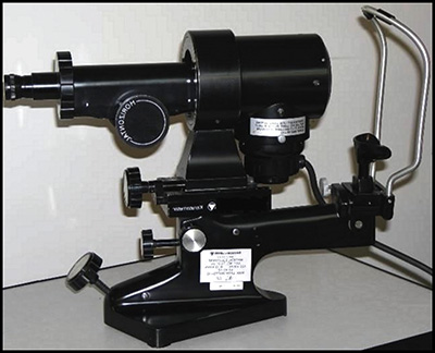
Following this basis and using the ability of the anterior corneal surface to behave as a convex mirror, in 1854 Helmholtz created the first true keratometer, also called ophthalmometer. Before this, some authors (Mandell, Ramsden, Kohlrausch) had tried to developed an apparatus for determining corneal curvature, creating some kind of prototypes. The Helmholtz keratometer projects four points onto the cornea, creating a reflected image, which can be analysed and converted to corneal radius data by using an equation that considers distance from mire to cornea, image and mire size. In 1881, Javal and Schiotz improved Helmholtz laboratory apparatus and built an ophthalmometer designed for clinical use (Fig. 1.12). Although keratometers are still used commonly in clinical practice, it has important limitations:
- It performs measurements of the central 3 mm, accounting only for 6% of the corneal surface.
- It assumes that the cornea has a perfect spherocylindrical shape, which is not true.
- Information from periphery is not provided.
- It gives no information of the central zone inside the four points measured.
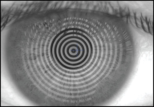
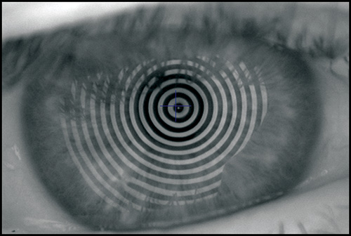
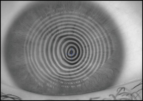
The keratoscope let us examine a much greater area of the cornea. Clinical keratoscopy has been used since 1870, when Placido studied the corneal surface by observing the corneal reflections of a series of illuminated concentric rings (known as Placido's rings) (Fig. 1.13). In 1896 Allvar Gullstrand incorporated the disk in a self-developed instrument for examining photographs of the cornea by a means of a microscope and calculating corneal curvature by means of a numerical algorithm. Depending on the distance between the concentric rings, the examiner can evaluate qualitatively the corneal shape.
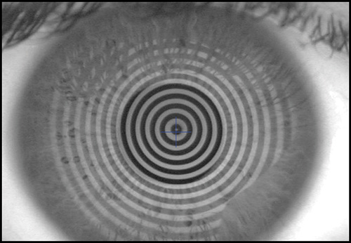
A steep area of the cornea causes a crowding of the mires at this area, while a flat cornea makes the opposite effect. Irregularity of the surface is seen as mire distortion.
In the 1980s, photographs of the projected images were hand-digitalized and then analysed by a computer. However, the automation of process and the image capture by a digital camera became soon a reality. Advances in video and personal computer technology made it possible to instantaneously acquire and analyze high quality images. These improvements made quantitative keratoscopy 8practical for routine clinical use. The Corneal Modeling System (CMS) produced by Computed Anatomy became the first widely used computerized videokeratoscope.
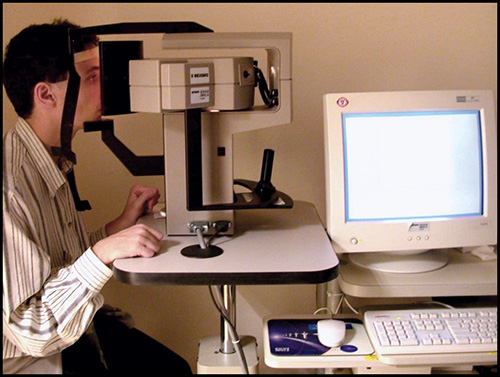
In an effort to improve accuracy and avoid the assumptions necessary for computerized videokeratoscopy, new technologies (projection systems) have appeared commercially in the last years, such as rastereography, laser interferometry, Moiré interference and slit-scan systems (Fig. 1.14). These systems directly measure the true shape of the anterior corneal surface in terms of height, not from curvature. From these measurements slope, curvature and power can be calculated.
Measurement Procedure
Corneal topography is a noninvasive method for determining the shape of the cornea. Each one of the commercially available devices has a specific method of operation, although some aspects are common.
Placido-based Systems
The Placido-based systems require an intact epithelial surface and tear film in order to obtain accurate and reliable measurements. The patient is sat facing a bowl containing the projected pattern which is focused on the anterior surface of the patient's cornea. The pattern reflected off from the cornea is analysed by a computer that provides data about the geometric configuration of the cornea in different kind of numerical and graphical formats.
Some of the errors that examiner can make using a Placido-based system are the following: focusing errors (Fig. 1.15), alignment (Fig. 1.16) and fixation errors (that could induce wrong levels of astigmatisms), wrong calculation of the position of the center from the small central rings, increased inaccuracy toward the periphery due to the lack of accuracy of the preceding points. We can conclude that critical points for a precise measurement are accurate alignment, centring and focusing. These issues depend on the ability of the examiner to take a good measurement.
There is another potential source of errors. It is essential for obtaining a good exam that the tear film forms a smooth layer over the irregular corneal epithelium. Tear film break-up causes mistracking of the mires and artifacts in the corneal map that appears as irregularity areas or false irregular astigmatism. For example, a dry patch could be associated with an area of focal flattening in the corneal map (Fig. 1.17). In order to avoid disturbing of the tear film, corneal topography should be performed before giving dilating drops and taking intraocular pressures.
In addition, there are a variety of complex surfaces that are very difficult to characterize. Errors greater than 4 D may occur in very steep or flat corneas, keratoconus with local steepening, sharp transition zones after uncomplicated refractive surgeries, diffusely irregular surfaces after penetrating keratoplasty, and complex surfaces after decentered ablations in refractive surgery or central islands. These complex cases may be easily identified on the raw image of the Placido rings projected onto the cornea. When there are abnormalities in tear film break up, the raw image is also very valuable.
The presence of areas which are not analysed on the corneal maps may be due to the configuration of the nose or the position of the eyelids (Fig. 1.18). To avoid these artifacts, it is important to instruct the patient to keep the eyes wide open and to maintain a good position and fixation.
Non Placido-based Systems
The accuracy and reproducibility of rastereography system is in the range of Placido-based system, but the advantage is that the former do not require an intact epithelial surface. A rastereography system projects a grid of known geometry onto the cornea through a cobalt blue filter. Topical fluorescein is used to stain the tear film. Then, the system calculates elevation or height by evaluating the distortion of the grid lines. From elevation data obtained across the full corneal surface, curvature data is derived by means of a specific algorithm.
In the slit-scan systems, a slit is projected sequentially onto the cornea at different angles. This is the basis used by the Orbscan corneal topography system. A high-resolution video camera captures 40 light slits projected onto the cornea. The diffuse reflection is obtained from the cornea, iris, and lens. By triangulation, data is obtained from the anterior and posterior surfaces of the cornea and from other structures. These issues permits this instruments to calculate anterior chamber depth or full pachymetry of the cornea. The accuracy and repeatability of this instrument is reported to be below 10 µ and it is significantly dependent on many factors, such as 10movement of the patient's eye, stability of tear film, ability of patients to keep the eyes wide open, corneal transparency, and the presence of corneal abnormalities. One of the limitations of slit-scan system is the longer time of image acquisition in comparison with any of the other commercially available instruments. In the other hand, it brings the possibility to characterize the posterior corneal surface. This issue is important for the detection of incipient keratoconus conditions.
ANALYSIS OF THE CORNEAL TOPOGRAPHY DATA: CORNEAL MAPS, DESCRIPTORS AND INDEXES
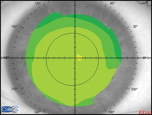
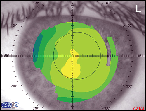
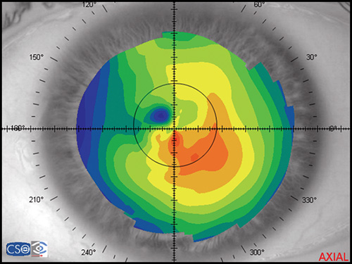
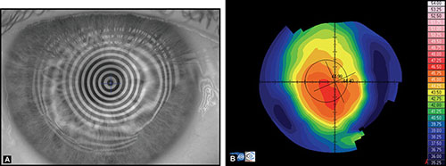
Corneal topography provides a great amount of information regarding the corneal surface. By representing this data as a colour-coded map, an experienced clinician can quickly evaluate corneal shape and other features closely associated with shape. A corneal map has a color scale that assigns particular color to certain keratometric dioptric range. Steep areas normally are represented by warm colors (red and orange) while flat areas are represented by cool colors (green and blue) (Fig. 1.19).
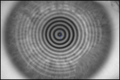
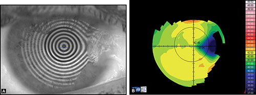
Before examining the color-coded map, it is critical to check the raw image of Placido rings projected on the cornea. It is important to confirm that the unprocessed data is reliable, as further analysis is based on these data (Fig. 1.20).
If an irregular videokeratoscope image is present, it can lead to wrong interpretation of the corneal map. Therefore it is necessary to find out the causes of this special corneal configuration to avoid misleading information.
Topographic Displays: Corneal Maps
There are different kinds of maps that provide different data from the same corneal shape. Each one of them has its own indications and limitations:
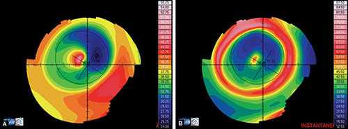
- Axial or sagital map (Fig. 1.21A): Despite its limitations, it remains the most widely recognized map because it is easy to understand. Colors visually correspond to flatness and steepness. The axial map measures the radius of curvature supposing a center of rotation on the axis of the videokeratoscope (the center of curvature of all the points of the particular surface lies on the same axis). It provides a general view of the curvature profile of the cornea, but the localized changes in curvature and peripheral data are poorly represented.
- Instantaneous or tangential map (Fig. 1.21B): It is more sensitive and represents local changes and peripheral data much better than axial maps do. The radius of curvature is calculated by referring to its neighbouring points, not to the axis of the 11videokeratoscope. These maps best identify corneal pathology such as ectatic disorders or surgically induced changes.
- Refractive map (Fig. 1.21C): It is useful when assessing the visual performance of a patient, for example after refractive surgery. It is calculated based on Snell's law of refraction, assuming optical infinity.
- Elevation or height map (Fig. 1.21D): It displays corneal height or elevation relative to a reference plane with a presumed assumption of the shape, which may be the best-fit sphere, best-fit asphere, average corneal shape, or even based on preoperative data. The same surface may appear different when it is mapped against different reference surfaces. Points above the reference surface are positive (hot colors) and points below the reference surface are negative (cool colors). It is very useful in detecting local irregularities, corneal ectatic diseases, or surgically induced changes.
- Irregularity map: It is similar to an elevation map, but it uses the best fit toric surface as reference.
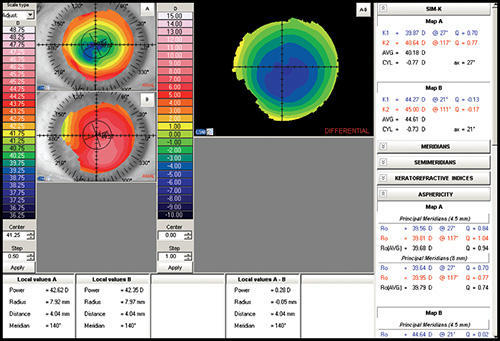
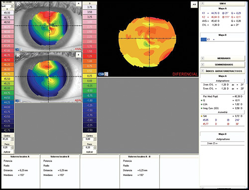
- Difference map: It shows the change in curvature or any other parameter between two maps (Fig. 1.22).
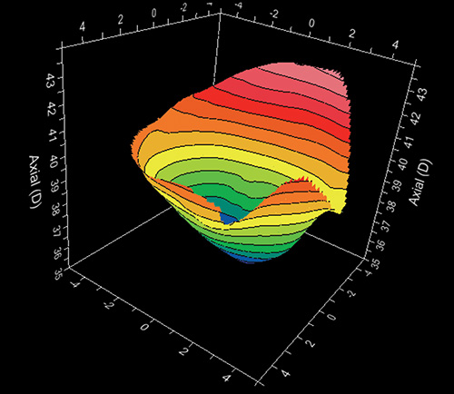
Depending on the kind of software associated to the videokeratocope, several other displays may be available as three dimensional maps (Fig. 1.23), relative maps, numerical views, profile views, etc.
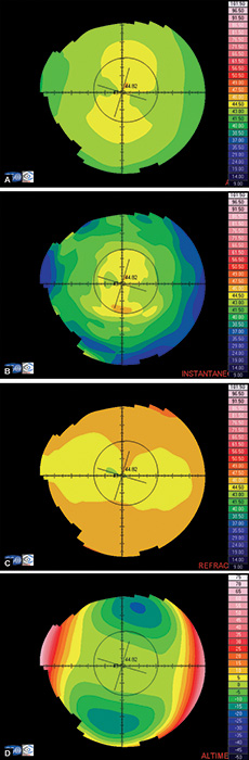
Figs 1.22A to D: Corneal topography analysed using different kind of maps: (A) Axial map, (B) Instantaneous map, (C) Refractive map, and (D) Elevation map
Color-Coded Scales
It is important when reading a corneal map to take into consideration the type of scale used. We cannot compare maps with different scales because it could lead us to a wrong clinical decision.
Absolute or fixed scale (Fig. 1.24A) uses the same color for the same curvature or elevation no matter what eye is examined. These maps allow direct comparison of two different maps buy it does not discriminate subtle changes of curvature.
Figs 1.24A and B: Axial map of a post-myopic LASIK using: (A) an absoluted or fixed scale, and (B) a normalized or variable scale
Normalized or variable scale (Fig. 1.24B) uses a given color for different curvatures or elevations on each cornea analysed, depending on the range for that particular cornea, determined by its flattest and steepest values. Maps with this scale cannot be compared directly and have to be interpreted based on the keratometric values from their different color scales. An advantage of this kind of scale is that it shows a more detailed description of the surface
Quantitative Descriptors of Corneal Topography: Corneal Indexes
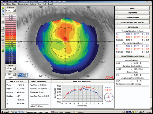
Computerized topography systems provide also a variety of numerical descriptors, usually called corneal indexes. These indexes are used to describe 13quantitatively different features of corneal topography. The most important ones are described below:
Simulated keratometry (SimK): It characterizes corneal curvature in the central area, correlating well with the measurements provided by the classic keratometer. It calculates the power and axis of the steepest meridian (K1) and the flattest meridian (K2), as well as the cylinder value (difference between K1 and K2).
Average corneal power: It is an area-corrected average of corneal power and it could be useful in the calculation of the appropriate intraocular lens.
Corneal asphericity (Q): It represents how much the curvature varies from the centre to the periphery of the cornea. A normal cornea tends to be prolate (becomes flatter toward the periphery). A prolate surface corresponds with negative Q values, whereas an oblate surface is represented by positive values of Q.
Shape factor (SF): It is another way of calculating corneal asphericity. It is calculated with the square of the value of the eccentricity, which can be obtained from the equation of the mathematical description of anterior corneal surface. The normal value ranges from 0.13 to 0.35 and it results negative after a myopic keratorefractive procedure.
Eccentricity This parameter has different names depending on the instrument considered. It characterizes the shape of the anterior corneal surface: a positive value is for prolate corneas, negative for oblates corneas, and zero for an ideal perfect spherical cornea. Average value in normal corneas is around 0.5.
There are some indexes that are specific of some kind of commercially available instruments. These indexes can be used in clinical practice as different mathematical estimates of the visual disturbance that can be expected to be caused by the amount of irregularities of the anterior corneal surface. Below we list some of them:
Surface regularity index (SRI): It is a measurement of the regularity of the corneal surface and it is higher as irregularity increases. Normal values are below one.
Potential visual acuity (PVA): It is an estimation of the expected visual acuity that is achievable based on corneal topography data.
Surface asymmetry index (SAI): It measures the difference between points located 180ª apart in a great number of equally space meridians. The more asymmetric the cornea is, the more SAI differs from zero.
Indexes for the detection of keratoconus: Several mathematical algorithms have been developed to aid detecting different states of keratoconus condition with high sensitivity and specificity. Some of them are the I-S value, the Differential Sector Index (DSI), the Opposite Sector Index (OSI), the Irregular Astigmatism Index (IAI), etc.
CLINICAL APPLICATIONS OF CORNEAL TOPOGRAPHY
The Assessment of the Refractive Patient
Corneal topography is mandatory in a refractive surgery setting:
- Preoperatively, to screen for irregular astigmatism, ectatic corneal disorders, and other abnormalities, and to monitor topographic stability following discontinuation of contact lens wear.
- Operatively, to determine surgical parameters (e.g., microkeratome settings) and to perform customized corneal ablations using topographic data.
- Postoperatively, to monitor and assess the surgical outcomes, detect the causes of visual complaints such as blurred vision, glare, or diplopia, and to assist the surgeon in correcting undesirable postoperative results when planning retreatment, as in decentered ablations, asymmetric healing, etc. However, recent studies show that corneal wavefront-guided procedures may provide better outcomes.14
Preoperative Evaluation
Detecting Irregular Astigmatism
Irregular astigmatism occurs when the principal meridians are not orthogonal or perpendicular to each other or when there are other rotational asymmetries that are not correctable with the conventional sphero-cylindrical lenses (Fig. 1.25). Corneal topography, especially photokeratoscope view and tangential map, plays a critical role in the detection of preoperative corneal irregular astigmatism.
Common causes of corneal irregular astigmatism include dry eye, corneal scars, ectatic corneal degenerations, trauma, pterygium, and surgery. Some causes of corneal irregularity may be discovered just with careful inspection of the photokeratoscope view showing irregular mires as in poor quality of tear film, subtle corneal scar, or epithelial basement membrane degeneration. The latter is a risk factor for corneal ecstasies after refractive surgery.
Minor degrees of irregular astigmatism are not uncommon and would not contraindicate standard refractive surgery. However, significant amount of irregular astigmatism can limit surgical outcomes due to poor predictability. Surgeons should be especially aware when dealing with rigid contact lens wearers who expect final uncorrected visualacuity to be similar to their previous best corrected visual acuity, as well as in patients who state that their vision with rigid lenses is significantly better than with spectacles.
Ensuring Refractive and Topographic Stability following Discontinuation of Contact Lens Wear
Corneal topography is essential for monitoring corneal topographic changes after discontinuation of contact lens wear to ensure stability before surgery. Contact lens should be discontinued prior to the topographic and refractive examination for the following durations: 5-7 days for standard soft lenses, 10-14 days for toric soft lenses, 2 weeks for rigid gas permeable lenses (RGP), and at least 1 month for polymethylmethacrylate lenses (PMMA). It is well understood that corneal refractive procedures should be deferred until the cornea returns to its baseline topographic state.
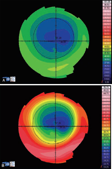
Contact lens wear can alter the shape of the cornea and induce corneal warpage (Fig. 1.26). Corneal warpage occurs more frequently in wearers of hard PMMA contact lenses or RGP contact lenses as a result of the mechanical pressure exerted by the lens, and corneal hypoxia.
There are at least four different forms of noticeable topographic changes that usually occur mixed with one or more of the other forms:
- Peripheral steepening. Surgeons must be aware of inferior corneal steepening (pseudokeratoconus) that resembles keratoconus. It is caused by a superiorly riding contact lens. In corneal warpage, the shape indexes do not indicate any keratoconic condition, and the flat K is not as steep as in keratoconus.
- Central flattening, that may be overlooked because the topography tends to look normal and symmetrical. Improper focusing can simulate central flattening, so checking photokeratoscope view seems necessary.
- Furrow depression, because of flattening under the edge of the contact lens. It is best seen with decentred rigid or hard lenses where the lens rides high or low in the stable resting position.
- Central molding or central irregularity. It is seen as a steepening under the region covered by the centre of the lens, and it is always irregular or patchy in appearance.
Ruling out Keratoconus and Other Ectatic Corneal Disorders
Ectatic corneal disorders, such as keratoconus (Fig. 1.27), pellucid marginal degeneration (Fig. 1.28), and keratoglobus, are considered contraindications to corneal refractive surgery. Corneal topography is of great importance in detecting these disorders.
Although keratoconus can be detected by qualitative methods, early or subclinical keratoconus are usually missed. Modern corneal topographers usually include software to predict the presence of keratoconus by quantitative methods in a more sensitive and specific way. Special effort is made in seeking for early keratoconus or “forme fruste keratoconus”, considered a contraindication to LASIK due to possible evolution into clinically significant keratoconus within months or years after the surgery.
Rabinowitz and Mc Donnell developed the first numerical method for detecting keratoconus using only topographic data. They established three criteria to determine whether the patient has keratoconus or not:
- The I-S value, which measures the differences between the superior and inferior paracentral corneal regions (3 mm above or below the corneal center).
- The maximum central corneal power (Max K)
- The power difference between both eyes.They obtained the following results:
- Keratoconus suspect: Central corneal power > 47.2 D or I-S > 1.4.
- Clinical Keratoconus: Central corneal power > 47.8 D or I-S > 1.9.
- Normal subjects had a power difference between the two eyes < 0.5 D
However, using only these simple measurements for keratoconus diagnosis presents specificity problems.
To solve the specificity problem, the new strategy must be able to detect and consider the unique characteristics of keratoconus maps, such as local 16abnormal elevations. The Keratoconus Prediction Index, developed by Maeda et al, is calculated from the Differential Sector Index (DSI), the Opposite Sector Index (OSI), the Centre/Surround Index (CSI), the SAI, the Irregular Astigmatism Index (IAI), and the percent Analyzed Area (AA). This method partially overcomes the specificity limitation.
Maeda et al also developed the neural network model, based on artificial intelligence. It is a much more sophisticated method for classifying corneal topography and detecting different corneal topographic abnormalities; it employs indexes that were empirically found to capture specific characteristics of the different corneal pathologies, including keratoconus. Further modifications in neural network approach developed by Smolek and Klyce supposedly produce 100% accuracy, specificity and sensitivity in diagnosing keratoconus.
Newer approaches for detecting early keratoconus (Fig. 1.29) and increased risk of ectasia after refractive surgery include patterns and indices based on the anterior or posterior elevation best fit sphere maps, obtained from Orbscan ®. However, further studies are needed to assess the performance of the topography elevation criteria in detecting keratoconus. It is known that the cone of the keratoconic cornea appears as an area of increased elevation surrounded by concentric zones of decreasing elevation. Two indices have been proposed to screen keratoconic corneas based on the Orbscan system:
- Maps with posterior elevation greater than 40 µm between patient cornea and best-fit sphere. Posterior corneal elevation may be the earliest sign of “forme frustre keratoconus”
- Maps with four or more colors within the central 3-mm area are judged abnormal in screening using the 10- and 20- µ interval color scales for the anterior and posterior elevation maps of the scanning slit topography, respectively.
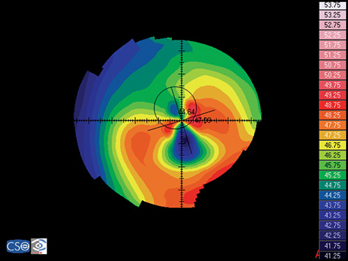
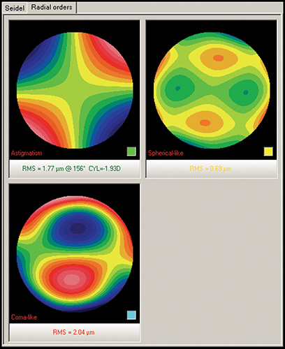
Keratoconic eyes exhibit significantly more ocular higher-order aberrations due to an increase of corneal higher-order aberrations compared to normal eyes. Coma-like aberrations were dominant compared with spherical-like aberrations in keratoconic eyes (Fig. 1.30), although both were significantly higher than in normal subjects. Wavefront sensing could also help to differentiate keratoconic eyes from normal eyes by analyzing the characteristics of the higher-order aberrations. The corneal wavefront aberration, which is the component of the total ocular wavefront aberration attributed to the cornea, can be derived from the corneal topographic height data.
Specifically, the calculation of wavefront aberrations is performed by expanding the anterior corneal height data into the set of orthogonal Zernike polynomials.
To summarize, corneas with” forme fruste keratoconus” or other ectatic disorders have increased risk of post-LASIK ectasia. Clinicians may employ one of the several methods noted above. However, it is important to remember that there is no approach that guarantees correct discrimination of all normal and ectatic corneas. Therefore, if an ectatic disorder is suspected, LASIK will not be safely performed.
Operative Evaluation
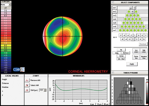
Currently, the vast majority of interest and research surrounding customized corneal ablation centers on utilizing the wavefront data and/or a combination of wavefront and topographic data. The corneal wavefront aberration, which is the component of the total ocular wavefront aberration attributed to the cornea, can be derived from the corneal topographic height data (Fig. 1.31). Specifically, the calculation of wavefront aberrations is performed by expanding the anterior corneal height data into the set of orthogonal Zernike polynomials.
Postoperative Evaluation
Although Corneal Topography is an excellent tool in assessing quality of the surgery and optical performance, its main indication after refractive surgery is to determine the cause of visual complaints including visual impairment.
When evaluating postoperative topographic maps, it is useful to examine several different kinds of maps:
- The axial map is useful because the patterns are familiar and abnormal patterns are readily detectable.
- The tangential map provides more precise information when evaluating local irregularities.
- The elevation map may reveal local variations in height that may suggest asymmetry that can contribute to loss of quality of vision.
- The difference map is used to assess the accuracy of centration.
Normal Topographic Changes after Refractive Surgery
Keratorefractive procedures attempt to alter the curvature of the central and mid-peripheral cornea, and usually have a minimal effect on the corneal periphery. The area in which the curvature is modified is called the optical zone. This tends to be surrounded by a small zone of altered curvature before normal cornea is reached at the periphery.
Postradial Keratotomy (RK)
Radial keratotomy (RK) is used to correct myopia by placing multiple deep radial incisions in the midperiphery and leaving a central clear zone (optical zone). These incisions cause a flattening of the central cornea, surrounded by a bulging ring of steepening called the paracentral knee or inflection zone that is situated at the 7 mm zone. This increases asphericity and corneal irregularity.
A very typical finding in these corneas is a topographic pattern with a polygonal shape (Fig. 1.32), which is seen in over a half of them. The polygons include squares, hexagons and octagons, depending on the number of incisions. The angles of the polygons correspond closely to the central ends of these incisions.18
Postastigmatic Keratotomy (AK)
This technique is a simple modification of the radial keratotomy that is used to correct astigmatism. Instead of placing incisions radially on the cornea, incisions are strategically placed on the steepest meridian. The incisions induce a flattening in that meridian, but provoke steepening in the perpendicular meridian, in a process called coupling. The astigmatic change achieved is the sum of the flattening in one meridian and the steepening in its perpendicular meridian.
Postphotorefractive Keratotomy (PRK)
Photorefractive keratotomy (PRK) is a procedure that uses a kind of laser (excimer laser, a cool pulsing beam of ultraviolet light) to reshape the cornea. To correct myopia, the excimer laser flattens the central cornea by removing tissue in that area. To correct hyperopia, the optical zone needs to be steepened by removing an annulus of tissue from the mid-periphery of the cornea. Regular astigmatism is corrected by differential ablation of tissue in the steeper meridian.
The topographic pattern in myopic corrections shows an oblate profile, with flattening of the central cornea (Fig. 1.33). The treatment zone is usually well delineated by the close proximity of adjacent contours at its edge, especially in the next days following the procedure during the first period of overcorrection.
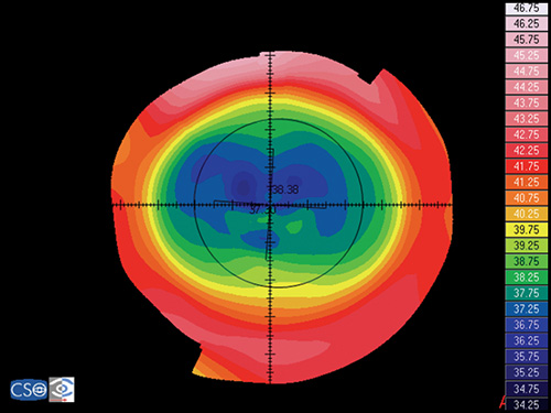
Later on, wound healing partially fills the ablated area. Hyperopic corrections have a pattern of central steepening surrounded by a ring of relative flattening at the edge of the treatment zone (more prolate profile). In astigmatic treatments, the treatment zone is oval.
Postlaser In Situ Keratomileusis (LASIK)
LASIK is an excimer laser procedure like PRK, but instead of superficial ablation, the cornea is ablated under a superficial corneal flap in order to minimize the influence of the epithelium and to enable stromal wound healing in a more predicted fashion. The topographic patterns for myopic (Fig. 1.34) and hyperopic (Fig. 1.35) corrections are the same as in PRK. However, overcorrection is not as large, and topographic stability is obtained earlier.
Postlaser Thermal Keratoplasty (LTK)
In laser thermal keratoplasty (LTK), a Holmium laser is used to heat stromal collagen in a ring around the outside of the pupil. The heat causes the tissue to shrink, producing a zone of localized flattening centered on the spot, and a surrounding zone of steepening. This bulging effect of the central cornea makes it possible to correct hyperopy (Fig. 1.36). The typical topographic pattern shows the central corneal steepening and a ring of flattening overlying the spots.19
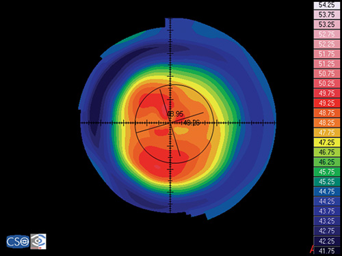
Figs 1.36A and B: Post-LTK corneal topography examination: (A) raw videokeratoscope image; (B) axial map
Abnormal Topographic Patterns after Refractive Surgery: Complications
Visual complaints after refractive surgery may be due to surface anomalies, which are too subtle to be detected on biomicroscopic examination, but can be revealed by corneal topography.
- Decentrations can be identified by the relatively asymmetric localization of the treatment area (Fig. 1.37). It is a shift of the centre of the ablation pattern form the pupil or visual axis to a more eccentric location. To be clinically significant, decentrations of current large diameter (6 mm) optical zones, have to be over 1 mm, unless the patient has relatively large pupils. Decentrations should be differentiated from irregular wound healing, because the former shows a decentred zone on early corneal topography.
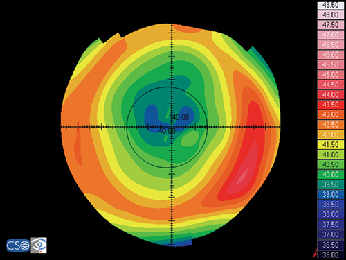
- Central island shows a central area of relatively less flattening measuring >1.0 mm in diameter and >1.0 diopter in power, and not extending to the periphery (Fig. 1.38). The central island is surrounded around its entire periphery by areas of greater power diminution. This area of underablation causes blurred vision, halos, and decreases corrected and uncorrected visual acuity.20
- Keyhole shows topographic regions, quantitatively measuring >1.0 mm in size and 1.0 diopter of relatively less flattening, extending in from the periphery of the ablation zone in one meridian.
- Focal irregularities or irregular astigmatism, refers to irregularities in the cornea surface that do not follow the regular “bow tie” pattern of astigmatism (Fig. 1.39). Most of the times they are produced by an inhomogeneous laser beam or an irregular process of corneal healing.
- Corneal ectasia. Topography shows irregular astigmatism often with inferior steepening of the cornea (Fig. 1.40), and posterior corneal ectasia on the posterior surface elevation map.
- Epithelial in-growth at the periphery of the flap-stromal interface produces an area of steepening surrounded by an area of marked flattening making the corneal surface more irregular (Fig. 1.41). This is seen in LASIK procedures.
Preoperative and Postoperative Assessment of Intrastromal Corneal Rings
Corneal topography is also very valuable in the assessment of intrastromal corneal ring implantation.21
The intrastromal corneal ring inserts act as passive spacing elements that shorten the arc length of the anterior corneal surface and therefore flatten the cornea. Corneal topography demonstrate that general flattening of the central cornea occurs after placement of ring and ring segments, but the normal positive asphericity of the cornea is maintained. The ring itself can be identified in the topographic map as a peripheral annulus of local steepening, surrounding, as already mentioned, a flattened central cornea (Figs 1.42A and B).
According to the FDA, intrastromal corneal rings are intended for the reduction or elimination of mild myopia (-1.00 to -3.00 D spherical equivalent at the spectacle plane) and they may now be used to reduce irregular steepening (irregular astigmatism) caused by keratoconus.
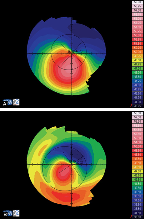
Fig. 1.42: Intracorneal rings implantation in a keratoconus eye. (A) preoperative axial map; (B) postoperative axial map
Therefore, intrastromal corneal rings are also intended for patients with keratoconus who are no longer able to achieve adequate vision using contact lenses or glasses and for whom corneal transplantation is the only remaining option.
In a recent study, Intacs (a model of intracorneal ring), provided better results in visual acuity and corneal topography quality and significantly reduced the spherical equivalent in eyes with keratoconus with relatively low mean K values (< or = 53 D) and a relatively low spherical equivalent. In contrast, when performing the procedure in advanced keratoconus (mean K-reading > or = 55 D), poor results can be anticipated.
The Assessment of the Corneal Astigmatism after Keratoplasty
Corneal topography is helpful in evaluating and managing patients following penetrating keratoplasty. Its main indications are:
- Evaluating unexplained decreased visual acuity after keratoplasty.
- Planning how to reduce high astigmatism after surgery. Different options are arcuate incisions in the highest power meridian, compression sutures in the lower power meridian, or refractive surgery with LASIK or PRK.
- Guiding selective suture removal to reduce astigmatism in graft patients.
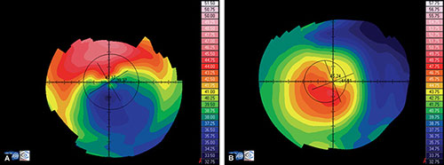
Different patterns of corneal shape result after penetrating keratoplasty, the most frequently seen are:
- Homogeneous, in corneas with less than 1.25 D of topographic astigmatism.
- Orthogonal symmetric toric bow tie (Fig. 1.43), showing an astigmatic pattern equal to or greater than 1.25 D, with equal slopes (less than 1D of difference) of the hemimeridians along a single meridian.
- Orthogonal asymmetric toric bow tie, showing an astigmatic pattern equal to or greater than 1.25 D with unequal slopes (more than 1D of difference) of the hemimeridians along a single meridian.
- Nonorthogonal toric bow tie, showing that the principal meridian's half bow ties are misaligned by more than 10° from 180°.
- Steep and flat, showing a cornea that is steeper on one side and progressively flattens toward the other side.
- Irregularly irregular, showing multifocal patterns of steepening or flattening not meeting the specific criteria of any other pattern previously described.
Although we have mentioned penetrating keratoplasty, the same patterns can be seen in lamellar keratoplasty, such as in deep anterior lamellar keratoplasty. Deep endothelial lamellar keratoplasty does not generate postsurgical astigmatism (Fig. 1.44).
Applications in Cataract Surgery
Corneal topography has become a useful tool when pursuing excellence in the outcomes of cataract surgery:
- To plan the place of the incision in phacoemulsification, in order to reduce postsurgical astigmatism, or even to correct preoperative astigmatism.For instance, it is known that an incision between 9 and 12 o'clock generates less astigmatism than 12 o'clock incisions. It is also well understood that to prevent astigmatism postoperatively, the incision should be placed at the steepest meridian in eyes with preoperative astigmatism greater than 0.5 D.
- To evaluate and plan the surgical approach in postoperative astigmatism.
- To predict corneal power in eyes with prior keratorefractive surgery.In eyes that have undergone previous keratorefractive surgery, accurate IOL power calculation remains a challenge due to inaccurate estimation of corneal power since standard keratometry or simulated keratometric values from topography cannot accurately measure the corneal curvature. Various methods have been developed to improve the accuracy of corneal power estimation. The clinical history method has been shown in general to be an accurate method for corneal power calculation; however, unacceptably large refractive surprises have still occurred. Also, historical data are mandatory in this method. Newer, more promising approaches involve calculating corneal refractive power from certain corneal topographic displays.
Evaluation of Irregular Astigmatism
The condition of irregular astigmatism is variously defined. To give a simple definition, irregular astigmatism is an astigmatic state not correctable by a sphero-cylindrical lens.
With the advent of computerized topographic systems, it is possible to distinguish two different types:
- Regularly irregular with either unequal slopes of the hemimeridians along a single meridian (the “asymmetric bow-tie”) or hemimeridians of equal slope but not aligned with each other (the “angled bow-tie” or nonorthogonal astigmatism). A combination of both patterns usually occurs.
- Irregularly irregular state is seen when even computerized topography cannot demonstrate a recognizable pattern, and the corneal surface can only be described as rough or uneven.Modern videokeratoscopy may define approximately 40% of normal corneas with a toric refractive error as possessing primary irregular astigmatism. Although some of these primary cases may have decreased best corrected visual acuity, clinically, the secondary forms of irregular astigmatism are more invalidating. Corneal topography has been used to evaluate the state and progression and to plan treatment of the following secondary forms:
- For visual impairment in corneal dystrophies and bullous keratopathy.
- To follow up corneal ulceration or abscess, and to determine the shape of the cornea after healing and scarring.
- To evaluate the visual effect of posttraumatic scarring, cause by incisions, excisions, burns, etc.
- To study postsurgical irregular astigmatism that may present after trabeculectomy, extracapsular lens extraction, keratoplasty, PRK, LASIK, LASEK, radial keratotomy, scleral encirclement, among others.
Diagnosis of Surface and Ectatic Diseases
Keratoconus
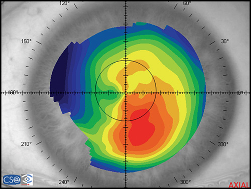
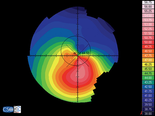
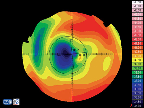
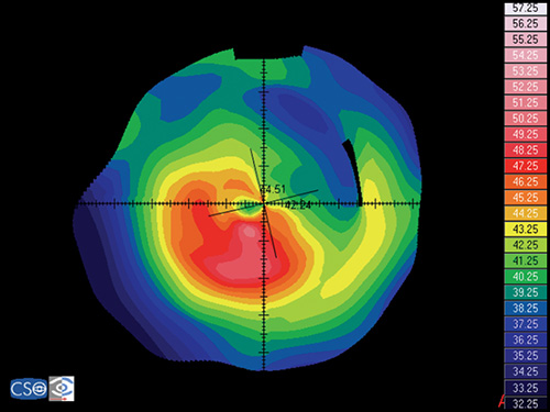
Keratoconus is characterized by a localized conical protrusion of the cornea associated with an area of noninflammatory corneal stromal thinning, especially at the apex of the cone (Fig. 1.27). The condition usually occurs in the second or third decade of life resulting in a moderate to marked decrease in visual acuity secondary to irregular astigmatism and corneal scarring.24
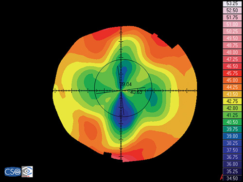
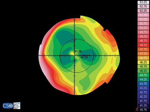
The typical associated topographic pattern is the presence of an inferior area of steepening usually in the temporal quadrant. In advanced cases, the dioptric power at the apex is at or above 55 D (Fig. 1.42A). The superior-nasal quadrant of the cornea is commonly the last to be affected, and thus an “island” of normal corneal topography often remains in this area even in the more advanced stages of the condition. In a small group of patients, the topographic alterations may be centred at the central cornea, showing an asymmetric bow tie configuration with the inferior loop normally larger than the superior loop (Fig. 1.45).
Keratoconic Corneas have three common characteristics that are not present in normal corneas:
- An area of increased corneal power surrounded by concentric areas of decreasing power,
- A inferior-superior power asymmetry,
- A skewing of the steepest radial axes above and below the horizontal meridian.
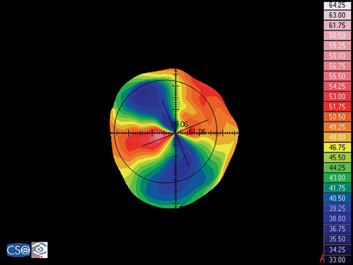
Pellucid Marginal Degeneration
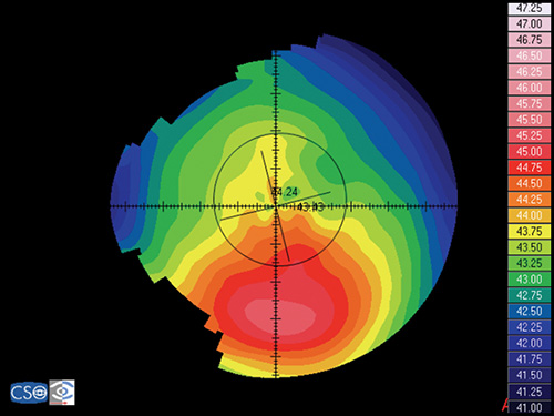
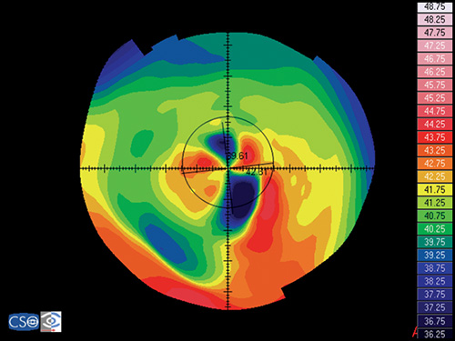
Pellucid marginal degeneration is a bilateral, non-inflammatory, peripheral corneal thinning disorder, characterized by inferior corneal protrusion, above a narrow band of clear, thinned corneal stroma that is concentric to the limbus.
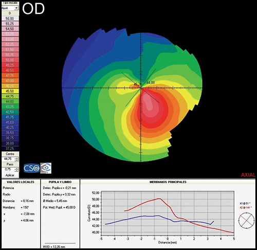
Fig. 1.45: Keratoconus, showing an asymmetric bow tie configuration with the inferior loop normally larger than the superior loop
In this disease the position of the ectasia is extremely peripheral and it presents a crescent-shaped morphology.
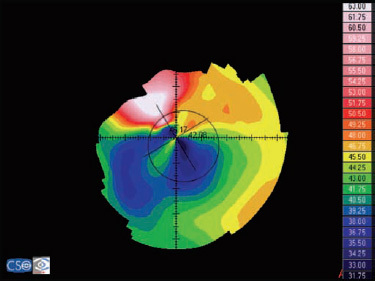
The videokeratographic pattern has a classic butterfly appearance that results in a flattening of the vertical meridian and a marked against-the-rule irregular astigmatism (Fig. 1.28).
Keratoglobus
Keratoglobus is a rare bilateral disorder in which the entire cornea is thinned most markedly near the corneal limbus, in contrast to the localized central or paracentral thinning of keratoconus. It is very difficult to obtain reliable and reproducible measurements in these cases due to the high level of irregularity and the poor quality of the associated tear film. Reliable topographic exams show an arc of peripheral increase in corneal power (steepening) and a very asymmetrical bow tie configuration.
Terrien's Marginal Degeneration
In Terrien´s marginal degeneration there is a flattening over the areas of peripheral thinning. When thinning is restricted to the superior and/or inferior areas of the peripheral cornea, a high against-the-rule or oblique astigmatism is seen. If the area of thinning is small or if the disorder extends around the entire 360º, central cornea may remain relatively spared with a spherical configuration.
Pterygium
It is a winglike mass of fibrovascular tissue extending from the conjunctiva to the cornea, usually are found more commonly nasally than temporally. When the growth of this pathological tissue is enough a flattening of the cornea at the axis of the lesion occurs causing a marked with-the-rule astigmatism, even of more than 4 D (Figs 1.46A and B). The wider the extension of the lesion and of the optical zone interested by it, the more marked this astigmatism. Corneal topography can monitor the evolution of the pathology and evaluate the surgical outcome.25
Other types of corneal pathology such as epithelial dysplasia and epithelial basement membrane disease can also be evaluated using corneal topography.
Contact Lens Fitting
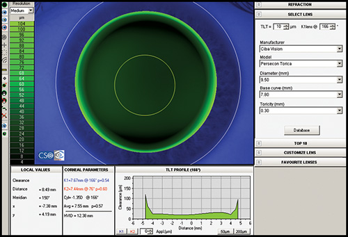
Most corneal topographers provide software that can design an appropriate contact lens based upon the topography (Fig. 1.47). The information corneal topography provides can greatly enhance the ability to manage complex contact lens fits and increase the overall success rate. It is practically mandatory when fitting contact lenses in patients with irregular astigmatism, for example after penetrating keratoplasty, after keratorefractive procedures, after corneal rings implantation or in advanced keratoconus, to locate precisely the corneal apex.
Other uses are for refitting warped corneas, and in orthokeratology.
Evaluation of Tear Film Quality
High-speed videotopography provides the possibility of quantitative measurement of tear-film dynamics and may have clinical value in the management of ocular surface disorders that present with tear film abnormalities such as dry eye.
BIBLIOGRAPHY
- Alio JL, Shabayek MH. Corneal higher order aberrations: A method to grade keratoconus. J Refract Surg 2006;22:539–45.
- Alio JL, Shabayek MH, Belda JI, Correas P, Feijoo ED. Analysis of results related to good and bad outcomes of Intacs implantation for keratoconus correction. J Cataract Refract Surg 2006;32:756–61.
- Bogan SJ, Waring GO, Ibrahim O, Drews C, Curtis L. Classification of normal corneal topography based on computer-assisted videokeratography. Arch Ophthalmol 1990;108:945–49.
- Boyd BF, Agarwal A, Alio JL, Krueger RR, Wilson SE, editors. Wavefront analysis, aberrometers and corneal topography, Highlights of Ophthalmology, 2003;
- Cairns G, McGhee CNJ. Orbscan computerized topography: Attributes, applications, and limitations. J Cataract Refract Surg 2005;31:205–20.
- Corbett M, O'Brart D, Rosen E, Stevenson R. Corneal topography: Principles and applications. BMJ Publishing Group, 1999;
- Courville CB, Smolek MK, Klyce SD. Contribution of ocular surface to visual optics. Exp Eye Res 2004;78:417–25.
- Dabezies OH, Holladay JT. Measurement of corneal curvature: keratometer(ophthalmometer). In Contact lenses: the CLAO guide to basic science and clinical practice, Kendall/Hunt Publishing Co, 1995;253–89.
- Demers PE, Steinert RF, Gould EM. Topographic analysis of corneal regularity after penetrating keratoplasty. Invest Ophthalmol Vis Sci 2002;43: 1783–90.
- Goggin M, Alpins N, Schmid LM. Management of Irregular Astigmatism. Curr Opin Ophthalmol. 2000;11:260–66.
- Goto E, Yagi Y, Matsumoto Y, Tsubota K. Impaired functional visual acuity of dry eye patients. Am J Ophthalmol 2002;133:181–86.
- Joslin CE, Wu SM, McMahon TT, Shahidi M. Higher-order wavefront aberrations in corneal refractive therapy. Optom Vis Sci. 2003;80:805–11.
- Karabatsas CH, Cook SD. Topographic analysis in pellucid marginal corneal degeneration and keratoglobus. Eye 1996;10:451–55.
- Kaufman H, Barron B, McDonald M, Kaufman S. Companion handbook to the cornea. Butterworth Heinemann, 1999;
- Klyce SD. Corneal topography and the new wave. Cornea 2000;19:723–29.
- Krachmer JH, Mannis MJ, Holland EJ, editors. Cornea. Surgery of cornea and conjunctiva. Elsevier-Mosby, 2005;
- Maeda N, Klyce SD, Smolek MK. Neural network classification of corneal topography. Preliminary demonstration. Invest Ophthalmol Vis Sci 1995;36:1327–35.
- Mejía-Barbosa Y, Malacara-Hernández, D. A review of methods for measuring corneal topography. Optom Vis Sci 2001;78:240–53.
- Miller D, Greiner JV. Corneal measurements and tests. In Principles and practice of ophthalmology, WB Saunders Co, 1994;7.
- Nemeth J, Erdelyi B, Csakany B, Gaspar P, Soumelidis A, Kahlesz F, Lang Z. High-speed videotopographic measurement of tear film build-up time. Invest Ophthalmol Vis Sci 2002;43:1783–90.
- Rabinowitz YS. Keratoconus. Surv Ophthalmol. 1998;42:297–319.
- Rabinowitz YS, Nesburn AB, Mc Donnell PJ. Videokeratography of the fellow eye in unilateral keratoconus. Ophthalmology 1993;100:181–86.
- Rao SK, Padmanabhan P. Understanding corneal topography. Curr Opin Ophthalmol 2000;11:248–59.
- Tanabe T, Oshika T, Tomidokoro A, Amano S, Tanaka S, Kuroda T, Maeda N, Tokunaga T, Miyata K. Standardized color-coded scales for anterior and posterior elevation maps of scanning slit corneal topography. Ophthalmology 2002;109:1298–302.
- Wang L, Koch DD. Corneal Topography and its integration into refractive surgery. Comp Ophthalmol Update 2005;6:73–81.
- Wilson SE, Ambrosio R. Computerized corneal topography and its importance to wavefront technology. Cornea 2001;20:441–54.
- Wilson SE, Klyce SD. Advances in the analysis of corneal topography. Surv Ophthalmol 1991;35:269–77.
- Wilson SE, Lin DT, Klyce SD, Insler MS. Terrien's marginal degeneration: Corneal topography. Refract Corneal Surg 1990;6:15–20.