

Ophthalmic lens theory is based upon the basic laws of Geometric Optics. The ophthalmic lenses are used to alter the path of light passing through it usually to correct some errors of the eyes. For theoretical calculations on ophthalmic lenses, light is assumed to travel in straight lines and that the incident light travels from left to right. It meets a surface that separates two media. What happens to the light, then, depends upon the nature of the surface and the two media on either side. In this chapter, we will consider these fundamental laws of physics and how they relate to the theory of spectacle lenses.
LAWS OF REFLECTION
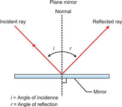
Light travels in straight line until it meets a surface that separates the two media. When light meets the surface, its behavior depends on the nature of the surface and the two media on either side. Light may be absorbed by the new medium, or transmitted onwards through it, or it may bounce back into the first medium. The bouncing back of light into the incident ray medium is called Reflection of light. The light may reflect specularly if the surface is acting as true mirror or it may reflect diffusely, scattering it in all directions if the surface is incompletely polished. In case of specular reflection, the reflected light obeys the laws of reflection, which states that:
- The incident ray, the reflected ray and the normal ray to the reflecting surface – all lie in the same plane.
- The angle of incidence equals the angle of reflection.
It follows from the laws of reflection that, when an object is placed in front of a plane mirror, the image formed by the mirror lies as far behind the mirror surface as the object lies in front. Also the straight line that joins the object and its reflected image is normal to the mirror surface (Fig. 1.1).2

LAWS OF REFRACTION
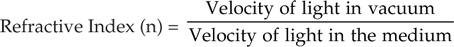
Refraction is defined as the change in direction of light when it passes from one transparent medium into another of different optical density. The incident ray, the refracted ray and the normal – all lies in the same plane. The refracted light undergoes a change in velocity. The ratio of the velocities of light in the first and second media is called the relative refractive index between the media, which slows with denser medium. The absolute refractive index of a medium “n” is defined as the ratio of the velocity of light in vacuum to the velocity of light in the respective medium:
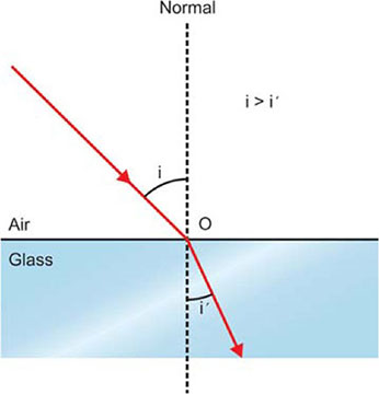
The Figure 1.2 illustrates a ray of light that is incident, in air at point D on the surface of a plane – solid glass block. The refractive index of the first medium (air) is denoted by n and the refractive index of the second medium (glass block) is denoted by n'. The angle of incidence that the incident ray makes with the normal to the surface at D is denoted by ‘n’ and the angle of refraction is denoted by n'. The laws of refraction (Snell's law) state that:
- The incident ray, the refracted ray and the normal to the surface at the point of incidence – all lie in one plane.
- The ratio of the angle of incidence, i, to the angle of refraction, i', is constant for any two media.
The most important application of this Snell's law of refraction is to determine the effect of prisms and lenses on the incident light, that is to determine the change in direction and the change in vergence produced by a lens.3
VERGENCE
Vergence is the term that determines the direction and power of light transmission. It is the wavefront of light of a particular position in a particular time. The vergence of light is defined by:

Where n | = | refractive index of the material. |
L | = | the distance in accordance with the Cartesian Sign Convention. |
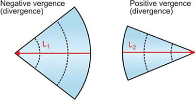
Since the distance L1 is measured from the wavefront and the light is traveling from left to right, it is a negative distance and the vergence is negative (divergent). L2 is positive since it is directed to the right from the wavefront (convergent) (Fig. 1.3). Parallel light rays are said to have zero vergence. The unit to measure vergence is “dioptre”. The change in vergence when the light encounters a refracting surface is equal to the power of the surface.
CURVATURE OF SURFACES
Most of the optical lenses have curved surfaces; the surface may be described as convex, if it bulges out of the material and concave if it is depressed into the material. Figure 1.4 illustrates a cross- sectional view of different curved forms. The measure of the shape of a curved surface is known as curvature. Spherical surface has uniform curvature in all its zones, whereas, surfaces other than spherical, the curvature varies in different zones and from one meridian to another.

The curvature of a spherical surface can be read with a simple instrument called “spherometer”, which measures the height of the vertex of the curve above a fixed chord (Fig. 1.5).
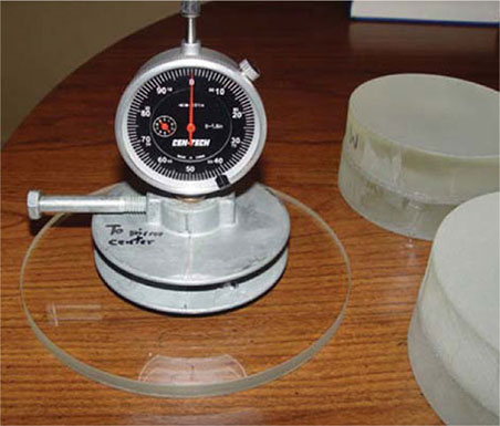
The common form of spherometer normally available is the “Optician's lens measure” which is calibrated for a refractive index of 1.523 and gives the dioptre power of the surface directly. More accurate version of this simple lens measure is used in surfacing laboratory and is known as “Sagometers” (Fig. 1.6).

FOCAL POWER
The total power of a lens or lens surface to bend light is referred to as its focal power. Units of focal power are expressed as “dioptre” and are related to the focal length of the lens. The relationship between focal length and focal power can be expressed by the formula:

Where F | = | Focal power in dioptre. |
f | = | Focal length of the lens in metres. |
n | = | Refractive index of the medium in which the light is traveling. |
Since, the spectacle lenses are always in air, the relationship can be simplified to:

THIN LENS POWER
In optical dispensing while calculating the power of the lens, the effect of the lens thickness is ruled out. The total thin lens power of the lens is the sum of its surface powers. For example, if a lens has a front surface power of + 8.00D and back surface power of − 4.00D, then its thin lens power is + 4.00D.6

Theoretically, we could make + 4.00D lens in any form as shown in Figure 1.7 in which the first form has both sides convex surfaces and is known as biconvex lens form. The second form which has one plane surface is known as plano convex lens form. The other forms in the figure, each has one convex surface and one concave surface and are known as curved or meniscus lenses. In practice, modern lenses are curved in form. The surface power of a curved lens may be different at its two principal meridians, in which case the lower numerical surface power is taken as the base curve.
The relationship between the two surface powers F1 and F2 and the total thin lens power of the lens F is:
F = F1 + F2
If the refractive index of the lens is denoted by ‘n’ and radii of curvature of the front and back surfaces are r1 and r2 respectively then the individual surface power is given by:

These two equations can be combined into the lens maker's equation:
F = (n − 1) (1/r1 − 1/ r2)
EFFECT OF THICKNESS ON LENS POWER
When the thickness of the lens is taken into account the actual power of the lens cannot be found from the simple sum of the surface powers, but it can be found by considering the change of vergence that the light undergoes after refraction at one surface and finally at the back surface. In case of a thick lens, the light after refraction from F1 will have a chance to travel a given distance before reaching F2 as it continues to travel through the lens thickness, it will have a slightly different vergence from when it left F1. It is this new vergence that F2 alters to produce an existing vergence.7
SIGN CONVENTION
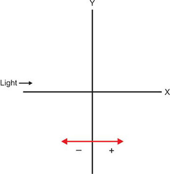
Light is assumed to be passing from left to right and the measurement taken in the course of light is taken as positive and the measurement taken against the course of light is taken as negative. All distances are measured from the vertex of the lens to the point in question. The sign convention is used to represent whether the corresponding surface is convex or concave (Fig. 1.8). It says that:
- Distances to the left are negative
- Distances to the right are positive
- Distances above the optical axis are positive
- Distances below the optical axis are negative.