

DEFINITIONS
The word ‘biomechanics’ is made up of two roots; bio, meaning life (greek, bios, way of life), and mechanics.
Mechanics is a branch of science that deals with forces and the effects of forces, specifically the motion and deformation of solid, liquid and gaseous matter.
The biomechanics of human movement’ is more likely to be concerned with some aspect of the human musculoskeletal system. Similarly, one might expect an article entitled. ‘The biomechanics of a rehabilitation electronic cycle’ to be concerned with the forces on the component that comprise the equipment.
The term biomechanics is a very useful label. For example an article entitled. ‘The mechanics of human movement’ could well be concerned with the logistics of installing escalators in public buildings or the problems of controlling an urban transit system or a social study of emigration and immigration.
If the term is to be defined then we need only modify that used for mechanics is a branch of science that deals with forces and the effects of forces on living systems and matter’, i.e. for our purposes it is the application of mechanics to the human body.
Motion may be defined as change in position of body with respect to the positions of other objects with the passage of time. The motion is the continuous change in the position of an object with the passage of time, so in order to study the motion of body, the position of a moving body at various instants of time should be observed. The simplest type of motion which needs to be explained initially is “motion in a straight line”. The motion by being relative in nature is explained with reference to a fixed point called origin. Like in our body 2the term proximal and distal are explained in terms of a fixed body part, i.e. head of the body.
Motion is the most common natural phenomenon, movement of vehicles, flowing of river, rumbling of leaves, flying of birds, movement of normal individuals, and diseased states like hemiplegics, paraplegics, etc. are the common examples of motion in nature. In fact, everything in the universe, right from the electron inside the atom to the largest galaxy in the universe is in motion.
TYPES OF MOTION
If a body covers equal distances in equal intervals of time, in the same direction then its motion is called uniform motion.
It is observed that a motor cycle starting from the rest, gradually gains its speed, it moves gradually move faster. It covers large distance in each successive seconds of its motion is called non uniform motion, e.g. vehicle starting from the rest are the good examples of non-uniform motion.
Galileo's Study on the Motion of Objects
On the basis of everyday experience of motion of objects around us. It is very easy to understand Galileo's conclusion. When we apply a small push to the wheel chair, we find that the wheelchair.
Newton's Law of Motion
After Galileo, Sir Isaac Newton (1642–1727) of England made a detailed and systematic study of motion of the bodies and formulated the three basic laws of motion. These laws after his name are called Newton's laws of motion.
First Law
A body continues in its state of rest or of uniform motion in a straight line until it is acted upon by an unbalanced external force.
Second Law
The force on an object is directly proportional to the product of the mass of the object and its acceleration and it acts in the direction of acceleration produced.3
Third Law
To every action, there is an equal and opposite reaction. Action and reaction act on different bodies but they act simultaneously.
These laws are based upon human experience about nature and are true everywhere in the universe.
The Newton's first law of motion contains following important points.
- Inertia is the basic property of all material bodies in the universe.
- It gives a qualitative definition of the force. It defines the force is that external influence.
- Which is necessary to change the state of rest or of uniform motion of the body?
- It also explains that only an external force can change its state of rest or of uniform motion in a straight line.
The Newton's second law of motion explains the relationship between force, mass and acceleration.
If ‘f’ indicates the force ‘m’ stands for the mass and ‘a’ for acceleration, then as per second law of motion.
f = m·a
Or f = kma
Where k is constant of proportionally and its value depends upon the unit chosen for Measuring force.
For one unit of force.
f = m·a
Force = mass x acceleration.
Alternatively, the law states that the acceleration of the body is directly proportional to the unbalanced forces acting on it and is inversely proportional to its mass. The direction of acceleration is the same as that of force,
i. e. a = f (where m is constant)
a = f (where f is constant)
Combining the above two equations
a = f
or
a = 1
Whenever two bodies interact, the force exerted by anyone of them is called action and that exerted by other is called reaction. The Newton's third law of motion deals with the interaction between pair of bodies and is explained as follows:
To every action there is an equal and opposite reaction. Action and reaction always act on different bodies. According to this law whenever a body exerts force on a body, the second body also exerts force on the first body, a force of equal magnitude but opposite direction. Thus we see that Galileo's discoveries and those of others contributed to Newton's laws of motion that form the current basis for mechanics and biomechanics
FORCE AND MOMENT OF FORCE
Force is defined as an external influence, which is necessary to change the speed or direction of motion of a body. The change in speed or change in direction of motion of body means the change in the velocity. Thus, we find that when a body in motion is undergoing a change in velocity then some external force must be acting on it.
Balanced Forces
When a number of forces acting on a body do not bring about any change in its state of rest or of uniform motion in a straight line, the forces are said to be balanced forces. In that case, the body behaves as if no net force is acting on it.
Unbalanced Forces
If a set of force acting on a body produce a change in its state of rest or that of uniform motion, then the forces are said to be a set of unbalanced forces. In this situation, all these forces do not completely balance or cancel out. There is always a net or resultant force left which acts on body and brings about a change in its state of rest or that of uniform motion.
Moment of Force
So far we have only considered the tendency of a force to move a body in a straight line, a form of motion, which is known as linear translation, but a force may also produce, or tend to produce, rotation of a body.5
In statics we must be able to predicts the tendency of a body to rotate under the action of any force even though actual rotation does not occur. The tendency of a force to produce rotation about any point is calculated by multiplying the magnitude of the force by the perpendicular distance between the line of action of the force by the perpendicular distance between the line of action of the force and the point. For example, the tendency of a weighted boot to rotate a patient's leg about the knee joint.
Moment of force = W × distance X,
where W is the magnitude of the gravitational force, i.e. the weight of the boot, and X1 is the perpendicular distance between the line of action of the weight and the point which we have assumed represents the axis of the knee joint.
Perpendicular means at right angles, i.e. at 90° to the action line of the force. The action line of the force in this specific case is that of a weight, which always acts vertically downwards. The unit of the moment of a force is Nm i.e. force x distance.
If the patient's leg is extended (Fig. 1.1), then although the weight of the boot has not changed, the perpendicular distance between the point of the knee axis and the line of action of the weight has increased consequently the moment of force is increased, so that now:
Moment of force = W × distance X2
Experience should suggest that the muscular effort required of a patient to hold his or her leg stationary when fully extended is greater than that required to simply allow the weighted boot to hang vertically below the axis of the knee joint (Fig. 1.1). In the latter case there is no moment of force because the action line of the weight now coincides with the knee axis the perpendicular distance has been reduced to 0, and thus

So far only horizontal and vertical forces have been considered but forces can act in any direction in space, and techniques for resolving and combining such forces must be used to analyze many common biomechanical problems. 6


Balance and Force
With reference to Figure 1.2A, apart from the need for balance of the weights on either side of the pivot point, the scales as a whole must be at rest. For example, even if the weight of the beam and the pans that comprise part of the scales is ignored, the weights in each pan (W) are both tending to fall towards the center of earth with an acceleration due to gravity, g = 9.8 m s−2 (Fig. 1.2b), as this is not happening and they are at rest we can conclude that there is another force, acting equal and opposite to the total downward force, i.e. and upwards force equal to W + W = 2 W (Fig. 1.2c). This upward force is being provided at the pivot joint.
Consider another example with reference to Figure 1.3A, if two blocks are stacked one upon the other and rest on the floor and each block is in static equilibrium then again the total downward force on 7each must be balanced by another force equal and opposite to the downward force.
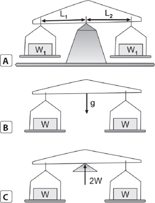
Figs 1.2A to C: Balance and scale; (A) W1 = W2 the scales are balanced; (B) Unsupported the weights and beam will fall to earth with an acceleration of g = 9.8 ms−2; (C) In equilibrium the scales are supported by a force at the Pivot point equal to 2W
Consider the top block. The total downward force in this case is the weight of the block W1 consequently the lower block must be applying an upward force equal to W1 (Fig. 1.3b).
Now consider the lower block (Fig. 1.3c). In this case the total downward force is its own weight, W2, plus the downward force arising from the top block, W1, i.e. the total downwards force W1 + W2 as this block is at rest then the floor must be applying an upward force, R, equal and oppositely directed to W1 + W2.
A biomechanical equivalent of the previous problem would be that of equilibrium of the human body with respect to the spine (ignoring muscle and ligament forces).
The first cervical vertebra must provide an upward force to maintain the head in equilibrium (Fig. 1.4A and B). The first sacral vertebra must provide a condition as in Figure 1.4C. Thus, as we proceed down the spine from the first cervical vertebra, the support 8provided by each vertebra to balance the superincumbent weight of body parts increases and the size of these vertebrae also increases from the cervical to the sacral region of the spine to provide the necessary strength for support of the body (Fig. 1.4d).

Figs 1.3A to C: Balance of stacked weights; (A) Forces acting on stacked weights; (B) Balance of the top weight; (C) Balance of the bottom weight
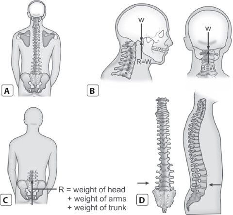
Figs 1.4A to D: Biomechanical example of stacked weights. Balance of the trunk and head; (A) Trunk and head: posterior view; (B) Balance of the head at the cervical region of the spine; (C) Balance of the upper body at the sacral region of the spine; (D) Increasing size of the vertebrae (arrows indicate position of second sacral vertebrae)

Figs 1.4A and B: The center of gravity (small circle) may lie outside the body. This concept is perhaps more obvious when related to an object such as doughnut (A), but it can also apply to the human body, depending upon the posture adopted, compare (B) and (A)
CENTER OF GRAVITY
Center of Gravity of the Human Body
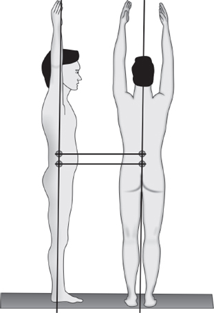
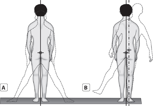
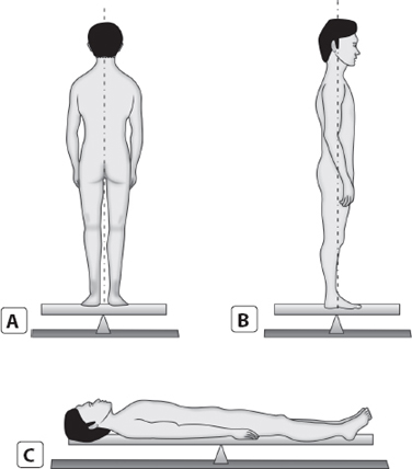
The human body is not rigid and fixed and consequently there is no unique single center of gravity for the whole body. However, if we minimize motion of the limbs and assume that our subject adopts what is referred to as a standard anatomical position. We can determine the effective center of gravity for the whole body for that position. For example when viewed in the frontal plane in a ‘standard anatomical position’ (Fig. 1.5A), as the body is reasonably symmetrical about the midline can envisage that it could be balanced on a pivoted board provide that the pivot was under the midline. When viewed in a sagittal plane body is not symmetrical about a convenient midline. Nevertheless, in theory a position could be found where the body could be balanced over the pivot (Fig. 1.5b). This would indicate a vertical line passing in front of the second sacral vertebra.10

Figs 1.5A to C: Board and pivot method of determining the position of the center of gravity of the human body in (A) the frontal plane, (B, C) the sagittal plane
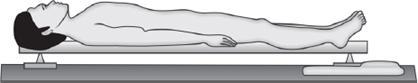
Fig. 1.6: Board and scales method of determining the position of the center of gravity of the human body
By combining this information from the frontal and sagittal planes we can find the location of a vertical line along which the center of gravity along this line, i.e. to find the height from, say the soles of the feet we must now lay the body down horizontally on a pivoted board and adjust the position of either the body or the pivot to achieve balance (Fig. 1.5c). In this position we would find that the position of the center of gravity in a sagittal plane is in line with the second sacral vertebra.11
In practice the position of the center of gravity of the whole body is more conveniently found by what is called the board and scales method (Fig. 1.6). In this method the body is still supported on a board but the board is now suspended on two supports rather than one pivot. By placing bathroom scales under these supports the force on each support is determined and by applying the principle of moments the position of the C of G is calculated.
Provided that the relative position of body parts is not varied too much the determination of the location of the center of gravity is useful in examining a number of problems. Figure 1.7 will raise the position of the center of gravity of the body a little but provided the arms are raised by equal amounts this will not affect the position of the line of gravity.
Similarly, spreading both legs apart will move the center of gravity of the body a little in the vertical direction but will not change the position of the line of gravity (Fig. 1.8A). raising only one arm or one leg will move the center of gravity in both the vertical and horizontal directions, i.e. the position of the line of gravity will shift (Fig. 1.8b).12
Figs 1.8A and B: Center of gravity and line of gravity; example 2, raising one limb will raise the center of gravity and move the line of gravity
When leaning forward, provided that the relative position of the body parts are not changed too much from the anatomical position we can assume the position of the center of gravity of the body is still just anterior to the second vertebra.
Notice, however Fig. 1.9, that the line of gravity remains vertical while the body is now inclined. In this case body weight would cause the body to topple over if some other external supporting from, such as that provided by the bath rail (Fig. 1.9) were not present. The introduces us to the criteria for stability.
Stability of Equilibrium
The classical example used to illustrated stability of equilibrium is the right circular cone Figure 1.10.
Stable Equilibrium
A body is said to be in stable equilibrium if when slightly displaced it tends to return to its original position of equilibrium under the action of the forces acting on it. For example, a cone with its bas resting on a horizontal plane is in stable equilibrium; if slightly displaced it tends to return to its original position (Fig. 1.10A).13
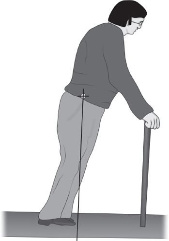
Fig. 1.9: Center of gravity and line of gravity; example 3, line of gravity in relation to base of support
Unstable Equilibrium
A body is said to be in unstable equilibrium if when slightly displaced it tends to be further displaced by the forces acting on it. For example, a cone if placed with its vertex in contact with a horizontal plane and its axis vertical is in unstable equilibrium if slightly displaced it will fall over (Fig. 1.10b).
Neutral Equilibrium
A body is said to be in neutral equilibrium if when slightly displaced it remains in its new displaced position. For example, a cone if placed with its curved surface in contact with a horizontal plane is in neutral equilibrium if slightly displaced it remains in its new position (Fig. 1.10c).
The general rule for ensuring stability is to keep the line of gravity within the base of support. 14

Figs 1.10A to C: Stability of equilibrium; (A) Stable; (B) Unstable; (C) Neutral. The stability of a right circular cone in three positions provides the classical example of the concept of stable, unstable and neutral equilibrium
Figs 1.11A to C: Extrinsic stability, body position and height of center of gravity; (A) Standing; (B) Sitting; (C) Lying
The larger the base and the lower the center of gravity the more stable the body (Fig. 1.11). When the line of gravity lies within the base of support the weight of the lies outside the base the weight of the body itself causes or contributes to unbalance. This applies the weight of the body itself causes or contributes to unbalance; this applies to both inanimate objects and the human body.
The angle of tilt needed to topple hoist is one of the measures used to check the safety of this particular type of patient lifting device (Fig. 1.12).15

Figs 1.12A to H: The external stability of a mobile hoist. (a–F) In general, the lower the C of G and the wider the base of a structure, the greater its stability. The force, F, required to tilt the structure will decrease as the angle of tilt increases until a position is reached where the weight of the structure itself is all that required to complete the tilting (c, F). the greater the angle required to reach this position the more stable the structure. The upper structure (a–C) is more stable than the lower structure (d-F). NB. If the force F is to produce tilting without sliding then an equal and opposite force F must act at the point of contact with the ground, provided by friction in the case of (B) and (E). (a–F) it can be seen that, although the C of G of the structure move relative to the ground with tilting, it remains in the same position relative to the structure. (g, H) in hoists where the body is suspended in a pendulum fashion, the patient's C of G moves relative to the structure so that at all times it is tending to be vertically below the suspension
Intrinsic and Extrinsic Stability
There are two important aspects to the stability of equilibrium of the human body. The first is the requirement for intrinsic, i.e. the stability of the many segments within the body. The second is the requirement for extrinsic stability, i.e. the stability of the whole body with respect to its base of support.16
Controlled muscular action around the joints of the spine and the lower limbs is an important feature in stabilizing the erect human body; a state of consciousness is necessary to remain upright. Nevertheless, the muscular activity is minimized if the line of action of the superincumbent weight of each body segment passes through each joint that provides a skeletal fulcrum. For example, with reference to Figure 1.13 if the line of gravity of the superincumbent weight of the body above either knee joint passes behind the effective axis of rotation of the knee then the turning effect of this weight, i.e. the moment of force will tend to flex that knee (Fig. 1.13A). Patients with ineffective quadriceps muscles thigh muscles would be unable to provide the necessary muscular effort to produce balance, i.e. the necessary counter moment of force and would consequently have an intrinsically unstable knee. In such cases some form of external bracing, such as a caliper may be required to provide intrinsic stability (Fig. 1.13b).

Figs 1.13A and B: Intrinsic stability; (A) line of gravity passing behind the knee joint body weight will tend to flex the knee. In a normal subject flexion will be resisted and controlled by the extensor muscles of the knee, providing intrinsic stability; (B) Intrinsic stability may be provided by external bracing, such as a caliper if the extensor muscles are weak
Summary
Two conditions for static equilibrium of a body
- There must be n net force acting in any direction
- There must be no net moment of force about any point in the body, i.e. the sum of the moments of force in a clockwise direction about any points. The requirement is referred to as the principle of moments.
The center of gravity (c) and (g) of an object is that point at which all the weight of the object may be considered to be concentrated and about which the object can, in theory, be exactly balanced.
When standing in the standard anatomical position the center of gravity to the human body lies just anterior to the second sacral vertebra.
A body is said to be in stable equilibrium if, when slightly displaced, it tends to return to its original position of equilibrium under the action of the forces acting on it.
The general rule for ensuring stability is to keep the line of gravity with the base of support. The larger the base and the lower the center of gravity the more stable the body.
Two important aspects to the stability of equilibrium of the human body are the requirement for intrinsic stability, i.e. the stability of the many segments within the body and the requirements for extrinsic stability, i.e. the stability of the whole body with respect to its base of support.
VELOCITY
Velocity is speed in a definite direction. It is a vector quantity; having direction as well as magnitude; Speed and velocity are measured in the same unit. In the CGS system, it is the centimeter per second (cm) and in the SI units it is the meter per second (m/s).
Consider a body traveling in a straight line with a uniformly increasing speed is average velocity.
The unit kilometer per hour km hr−1 is often used. To completely specify a velocity as distinguished from a speed, the direction should be given as 40 km hr−1 North-East or 30 m S−1 vertically upward.18
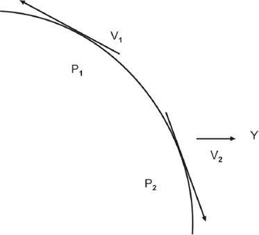
Speed may change only by a change in magnitude. Velocity is a vector, velocity may change either in magnitude or in direction (Fig. 1.14).
The velocity V2 is different from the velocity V1 because the direction are different although the magnitudes are the same. For example, two cars moving at a rate of 60 km/h in different directions have the speed but different velocities. A car may move around a circular track at constant speed but its velocity is continuously changing because the direction of motion is changing. Speed is the time rate of change of position of a particle without regard to the direction of motion. Velocity is the time rate of change of position of a particle in a specified direction.
Average Velocity
Consider a body traveling in a straight line with a uniformly increasing speed. A curve of displacement against time for such a body is shown in Figure 1.15A.
Such a curve is called a displacement time curve.
Take two points A and B on the curve at time t and t1 so that the displacement are x and x1 from origin O. Join AB. Draw AC and BD perpendicular to the time axis and AE perpendicular to BD. The BE represents the distance traversed in a time represented by AE.
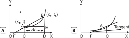
Figs 1.15A and B: Time displacement curves, Average velocity at any time interval is given by the slope of the corresponding chord
ACCELERATION
A particle has acceleration when its velocity changes with time. The change in velocity may be a change in their speed or direction or both, in all the three cases the body has acceleration. Thus acceleration is defined as the time rate of change of velocity and may be either positive or negative. If it is negative, it is sometimes called retardation.
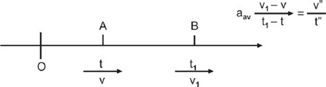
- Average acceleration in one dimensional motion, the particle move along a straight line (Fig. 1.16).
Let a particle move along x-axis starting from origin O. Suppose that a time t the particle is at A moving with velocity v and at time t1 is at B moving with velocity v1.
The average acceleration between A and B is given by
Where v″ = v1 − v is the change in velocity and t″ = t1 − t is the elapsed time. Thus, the average acceleration when the time interval t″ becomes very small.
FRICTION
Whenever, we try to push a body to make it slide or roll over the surface of another body, a force is required to act upon it. The magnitude 20of this force depends on weight and nature of the body and also upon the nature of the surface, upon which the body slides. Thus force of friction or simply friction may be defined as the opposition or resistance which comes into play when a body tends to move or actually moves over the surface of another body. This force always acts in a direction tangential to the surface in contact and opposite to the direction of the motion of the body. The tendency of this force is to destroy the relative motion (Fig. 1.17).
Types of Friction
There are two kinds of friction.
Static and Kinetic
Static friction is the force which resists setting the bodies in relative motion.
Kinetic friction is the force is the force which resists their being maintained in relative motion. Kinetic friction is also called dynamic friction.
Laws of Friction
Experiments on friction indicate certain general relations, the so called laws of sliding friction these experimental laws are not exactly obeyed but hold more or less approximately over a considerable range of applications.
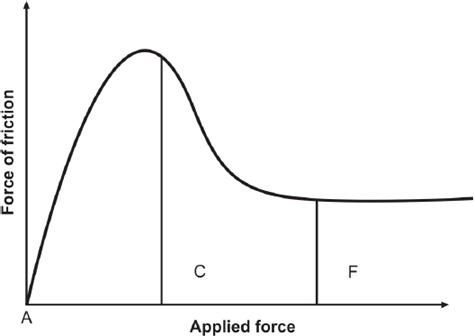
Fig. 1.17: Friction force drops from the highest limiting effect to a frictional effect, which is constant with time
- The force of sliding friction is directly proportional to the force pressing the surface together.
- The force of sliding friction is independent of the areas of the surface provided the force pressing the surfaces together is kept constant.
- The force of friction may be independent of the relative speeds of the surfaces for a considerable range of speed.
- The force required to keep an object moving with constant velocity when sliding over another body is less than the force required to set it in motion.
- The force of friction depends on the nature of the surfaces in contact.
WORK
In everyday life when a person applies a mental or a physical effort he says that he is doing work. A laborer standing with a stack of bricks in his hands applies physical effort in straining his muscles continually for holding the bricks against the pull of the earth but does not do any work. Similarly a student reading a book applies mental effort but he also does not do any work. Work is said to be done when force acting on a body produced in it, a displacement along the line of action of the force. Work is a scalar quantity.
Following two conditions must be satisfied- simultaneously for work to be done.
A force has to act on a body.
The point of application of the force should move along the line of action of the force.
USE OF STATICS
During the common activities of daily living the forces transmitted through the joints, limbs and tissues of the body can be well in excess of the body weight of the individual. When rising from a chair, forces on the knee joints can reach values some three or four times the value of 22body weight and in particularly unfavorable conditions, even higher. Those responsible designing or selecting furniture and equipment for the elderly and disabled should be aware of this as should those health professionals who treat and advise the elderly and disabled. Bending over the lift an object or a patient can generate forces in the lumbar region is poor. Understanding how the magnitude of the stress imposed on the back is related to the geometry of the lifter is an important step in understanding and preventing lower back and injury, a problem which, it is worth nothing, is as prevalent in healthcare workers, as it is in many other less well informed groups of workers.
When simply walking at a relatively normal speed, the forces transmitted through the joints of the lower limbs can rise and fall between two and five time body weight. Indeed, the force across the hip joint may be two and five times body weight, indeed, the force across the hip joint may be two to three times body weight when one is just standing still on one leg (Fig. 1.18); perhaps even more surprising, though, is the suggestion that a patient, lying in bed, may generate forces in the hip in excess of body weight by attempting to raise a leg clear of the bed. Before a therapist selects a nonweight bearing exercise or activity, for a patient to avoid premature stressing of an injured limb or joint, it is worth while reflecting on the fact that forces acting within the body may be much higher than one intuitively expects. This magnification of forces within the body is not something that is obvious but the mechanism can be better understood by the concepts of levers and moments of force, which are dealt with in that part of mechanics called statics.
In statics, the body (this term can refer to an inanimate object as well as the human body or parts of the body) is viewed as stationary, i.e. at rest, and certain rules that must govern forces acting on a body at rest are applied. This involves the concept of levers; it is a powerful and valuable concept that can be applied to many practical problems in remedial therapy. When an occupational therapist suggests that an elderly or disabled client uses a long handled tap rather a conventional one this is to provide good leverage (Fig. 1.18). Similarly when the physiotherapist applies manual resistance or assistance to the movement of patient's limb, by applying force at the end of the 23limb, the force required from the therapist is reduced as leverage is increased (Fig. 1.18c–d).
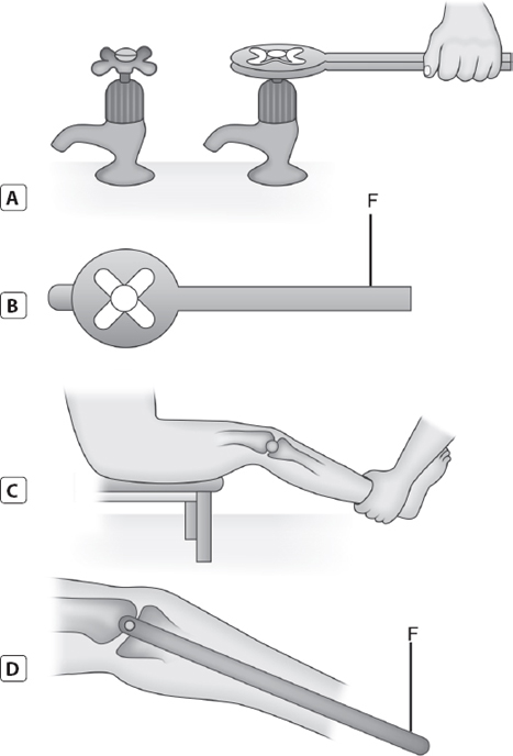
Figs 1.18A to D: The concept of levers, (a–B) Leverage provided by a long-handled tap. (C–D) leverage about the knee joint
When standing on one leg, the force on the supporting hip joint may exceed the apparent weight acting on the joint because of the effect of internal leverage (Fig. 1.18E–f). A patient with a painful hip may lean over to the affected hip, contrary to our intuition, in an attempt to eliminate this leverage effect (Fig. 1.18).24

Figs 1.18E to H: The concept of levers (e–F) leverage of body weight about the hip joint during unilateral stance. (g–H) Eliminating leverage about the hip joint by leaning over the joint
Although it has been stated above that in static the body is viewed as stationary. Fortunately, the methods of statics can be applied to moving bodies provided that certain basic rules are followed. In essence we analyze the moving body at instants in time when we can define and measure the geometry of external and internal forces that must be acting. In fact, examining the motion information for the therapist, this is the topic of kinematics.
USE OF KINEMATICS
Kinematics can be described as the geometry of motion. Maintaining the potential for motion or movement in patients who are otherwise ‘immobilized’ and restoring optimum capability for motion in patients is a major goal in many rehabilitation programmed. Judgments 25on what constitutes normal in many rehabilitation programmed. Judgments on what constitutes normal and abnormal motion require some form of statement from the observer. Kinematic provides a quantification and precision to these statements.
For example, in examining pathological walking patterns or the gaits of patients while it is still useful to identify characteristic limps it is proving more useful to use the systematic methods developed in kinematics. Parameters, such as length, displacement, angle and time can be estimated or measured and recorded. Observation is made on each body segment or joint (trunk, pelvis, hip, knee, ankle and foot in addition to the body as a whole.
This approach not only contributes to rationalizing the diagnosis of the origin of locomotors problems but also makes the comparison of treatment regimes and the recording of the progress of patients more universal and reliable that based solely on the subjective and personal experience of skilled clinicians.
The use of kinematics is not limited to gait analysis. The analysis of motion is the first step in examining another type of force which is relevant to the therapist – dynamic forces. Dynamic forces are dealt with in the branch of mechanics called kinetics.
USE OF KINETICS
Forces are required to start motion, to chance motion and, as in the case of the falling block of cast iron, to stop motion. The size of the force is directly related to both the mass of the object and the changes that occur in its motion. In gently placing the 1 kg mass on the foot there is little motion involved and consequently little change in motion required. The force on the foot in this case is just the weight of the block.
The dynamic force required to stop it moving may be several times the weight of the block. The more rapidly the block is stopped, i.e. the smaller the time interval, the greater the dynamic forces.
Appreciating how matter responds to force is also of practical use. The topics of structures, materials and human tissues, and the mechanics of fluids are introduced in chapter 6 and 8, respectively, but as one aim of the book is to show the integration of these disciplines 26an indication of their uses in health care is appropriate here. Mechanics is a branch of science that deals with forces and the effects of forces, specifically the motion and deformation of matter. Biomechanics is the application of mechanics to the human body.
Three important disciplines within mechanics are
- The mechanics of rigid bodies (statics, kinematics and kinetics)
- The mechanics of solid deformable bodies (solid materials and structures) and
- Fluid mechanics (liquid and gases).
During activities of daily living, forces transmitted through the joints, limbs and tissues of the body can be many times the body weight of the individual the concept of leverage (moments of force) explains this phenomenon.
Kinetics
Force, Acceleration, Mass, and Center of Mass
Newton's three laws of motion were discussed in some detail in chapter 2 and 3 and examples 3 below is a fairly straightforward example of the application of the force acceleration method of solving a kinetic problem. Example 4 introduces a slightly more complicated problem. Unlike a simple rigid body with a clearly defined center of mass. The human body is a system of interconnected parts with a less clearly defined center of mass. Newton's second law, F = m a, must now be seen as meaning that unless an external force acts on a body its center of mass cannot change its state of existing motion. When a swimmer jumps from a diving board, although s/she can twist and turn and in effect change. The relative position of the limbs and trunk by muscle action, this has no affect on the trajectory of the center of mass of the body, which has been determined at the instant that his / her feet lost physical contact with the diving board. Gravity alone now changes trajectory, as it is the only external force acting on his/her body ignoring air resistance.
Definitions of Key Terms
Kinematics is the branch of mechanics that is concerned with the phenomenon of motion without reference to mass or force. It may be described as the geometry of motion.27
Kinetics is the branch of mechanics that is concerned with motion, mass and the force that produce motion.
Statics is the branch of mechanics that is concerned with the description and analysis of forces that tend to cause motion.
Body is a terms used in mechanics to represent any object, animate or inanimate. The term rigid body is a theoretical concept used to represent a body whose shape and size are not influenced by external forces.
Magnitude means size and is specified by a number and a unit, e.g. 15 meters, 20 seconds.
Force is a push or a pull; it may be defined by restating Newton's first law of motion:
A force is that which changes or tends to change the state of rest or uniform motion of a body