

INTRODUCTION
Physics is an important component of the curriculum of postgraduate students. A thorough understanding of the physical principles of various pieces of equipment is essential in order to use them safely. This chapter covers the major areas of physics as applicable in anesthesia practice. In each main area, the various details are further explained in alphabetical order, except for some principles that need to be explained together for a better understanding.
- Compressed gases
- Vapors
- Fluids
- Diffusion/Osmosis
- Heat
- Humidity
- Electromagnetic spectrum
- Electricity
- Ultrasound
COMPRESSED GASES
Anesthetists use compressed gases in their day-to-day practice. At room temperature, some agents exist mostly as liquids and some only as gases. A nonliquefied compressed gas is a gas that does not liquefy at ordinary ambient temperatures regardless of the pressure applied. Oxygen and air are examples of such gases. Oxygen, when supplied at very low temperatures is a cryogenic liquid. A liquefied compressed gas is one that becomes liquid to a large extent in containers at ambient temperature and at pressures from 25 psig to 1500 psig (172 to 10,340 kPa). Examples include nitrous oxide and carbon dioxide. Different principles that require to be understood for safe use of compressed gases are detailed below.
Adiabatic Process
The behavior of gases depends on the constancy of pressure, temperature or volume. The relationship between these variables is described by ideal gas laws. For a change to occur in the state of a gas, heat energy is either added or taken away from the gas. If the state of a gas is altered without a change in heat energy, it is said to undergo adiabatic change. An adiabatic process describes the change in the state of gas which occurs without transfer of heat or matter between a system and its surroundings.
Adiabatic Expansion
If compressed gas expands adiabatically, heat energy is taken from the surrounding and cooling occurs. This principle is used in the commercial manufacturing of oxygen and cryoprobe.
Joule-Kelvin or Joule-Thompson effect: The phenomenon was investigated in 1852 by the British physicists James Prescott Joule and William Thomson (Lord Kelvin). When a high-pressure gas is released rapidly through a valve or porous opening, the resulting expansion leads to decrease in temperature. This can result in cooling of the gas which eventually liquefies. This principle is known as Joule-Kelvin principle and can be used for production of liquid air. By using the fractional distillation of liquid air (due to the different boiling points of nitrogen and oxygen), oxygen can be produced commercially.
The cryoprobe is used for rapid freezing of tissues in the treatment of skin lesions, in gynecology, and in ophthalmic surgery.
Adiabatic Compression
If a gas is rapidly compressed its temperature rises. When a gas cylinder connected to the anaesthetic machine is turned on too quickly the temperature rises in gauges and pipelines and in the presence of oil or grease may lead to a fire or explosion.

Atmospheric Pressure and Units (Table 1.1)
The atmospheric pressure is the pressure exerted by the atmosphere at sea level and is the result of the weight of atmospheric gases bearing down on the surface of the earth.
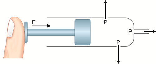
Pressure: Anesthetists make pressure measurements both in patients and in machines, and hence should have a good understanding of pressure and its units of measurement. Pressure is expressed as force per unit area (Fig. 1.1). The SI unit is Pascal; since this represents a tiny pressure, more commonly, kilopascal (kPa) is used. The other units commonly used are presented in Table 1.1. The relationships between gas volume, pressure and temperature of compressed gases is shown in Table 1.2.
Critical Temperature and Critical Pressure
Critical temperature is defined as the temperature above which gases cannot be liquefied by applying pressure. Critical pressure is the pressure at which a gas can be liquefied at its critical temperature (critical pressure of oxygen—49.7 atm). The critical temperature of nitrous oxide (N2O) is 36.5°C, and hence N2O exists as a liquefied gas in the cylinders at room temperature. The critical temperature of oxygen is – 118°C and hence at room temperature oxygen exists as compressed gas. Liquid oxygen (LOX) can only be obtained if the oxygen is cooled below its critical temperature and pressurized.
| |||||||||||||||||||
In order to maintain this temperature, special insulated and refrigerated containers are required for supply of liquid oxygen (Chapter 2).
Poynting Effect
Described by Poynting and also known as pseudocritical temperature. The Poynting effect refers to the phenomenon of physical properties of a mixture of gases, differing from the individual gases. The critical temperature of a gas including its boiling point is altered, when mixed with another gas.
The Entonox Cylinder
Oxygen at room temperature exists in gaseous state in compressed gas cylinders because it has a very low critical temperature. Nitrous oxide exists as liquefied gas at room temperature, since its critical temperature is higher. However, when nitrous oxide is mixed with oxygen (Entonox), nitrous oxide remains in a gaseous state even at a pressure of 137 atmospheres. This effect of oxygen which lowers critical temperature of the mixture (pseudocritical temperature), is attributed to the Poynting effect. This principle allows us to use Entonox cylinder to provide obstetric analgesia, analgesia to transport patients with long bone fractures and in dental practice.
Force (Relation to Pressure)
Force is that which changes or tend to change the state of rest or motion of an object. In SI system force is measured in newtons (N). A newton is that force which gives a mass of 1 Kg an acceleration of 1 meter per sec per sec (Kg.m.s-2). Force, pressure and area are interrelated. Force is pressure acting on unit area (Fig. 1.1). If force is applied over smaller area (like a smaller syringe) the pressure is 3higher. Similarly, high pressure acting over small area can be balanced by reduced pressure acting over larger area. This concept is used in the construction of pressure regulators (Chapter 3).
Gas Laws (see Table 1.2)
Avogadro's Hypothesis
Equal volumes of gases at the same temperature and pressure contain equal number of molecules. This number of particles is 6.022 × 10²³ and is known as Avogadro's number. One mole of any gas occupies 22.4 liters at STP and 24 liters at RTP (20°C at sea level). This principle is used to calculate:
- The contents of a cylinder containing liquefied gas
- The amount of vapor that can be generated from a given amount of volatile liquid
- The volume of CO2 absorbed by soda lime.
Boyle's Law
The first perfect gas law. Boyle's law states that at a constant temperature, the volume of a given mass of gas varies inversely with the absolute pressure. Another way to put the Boyle's law is to say that with any increase in the pressure of a gas at a constant temperature, the volume of the gas decreases. Similarly, with any decrease in the pressure, while maintaining a constant temperature, the volume of the gas will increase. Furthermore, any increase or decrease in the volume of the gas at a particular temperature will decrease and increase the pressure of the gas respectively. Two important practical uses of Boyle's law are:
- Calculation of volume of gas in a cylinder containing compressed gas (Chapter 2) and
- Body plethysmography where the subject is totally contained in an airtight chamber and attempt to breathe against an occluded airway. Changes in the alveolar pressure are recorded and compared with small changes in lung volume, derived from pressure changes in the plethysmograph. Application of Boyle's law then permits the calculation of lung volume.
Charle's Law
Second perfect gas law states that at a constant pressure, the volume of a given mass of gas varies directly with absolute temperature. This principle is used to calculate the contents of a cylinder containing liquefied gases (Chapter 2). As per this principle, the volume of a mole of gas at STP is 22.4 L and it becomes approximately 24 L when correction is made for RTP.
Gay Lussac's Law
Third perfect gas law: At a constant volume, the absolute pressure of a given mass of gas varies directly with temperature. As temperature increases in the cylinders, the pressure increases resulting in the possibility of an explosion. Hence, gas cylinders should not be exposed to extremes of temperatures and stored in cool places and regulations place a limit to filling density of liquefied compressed gas.
The Ideal Gas Law
The ideal gas law relates the four quantities: pressure, volume, moles and temperature.
Universal Gas Constant
The three (3) gas laws are combined to give the universal gas constant:
P*V = K1 | V/T = K2 | P/T = K3 |
P*V/T = universal gas constant “R”
Using Avogadro's hypothesis at constant T and P, the volume (V) = number of molecules (n).
So combining all the laws: PV = nRT
Measuring the change in the number of moles (n) of a gas in a stream gives a measurement of the number of atoms moving in the flow and is called molar or mass flow. This principle of ideal gas law enables one to understand the principle of partial pressure.
Dalton's Law of Partial Pressures
The Ideal Gas Law for a mixture of two gasses can be rewritten as:
PV = (n1 + n2) RT = n1RT + n2RT
The Dalton's law states that in a mixture of gases, the pressure exerted by each gas is same as the pressure exerted as if it occupied the container alone. The total pressure exerted by the mixture is equal to the sum of pressures exerted by individual gases. The pressure exerted by each gas is proportionate to the percentage of that gas in the mixture.
So partial pressure = Fractional concentration * Total pressure.
For example, if air is 20% oxygen and 80% nitrogen then for an atmospheric pressure of 760 mm Hg, the partial pressure of oxygen will be 152 mm Hg and the partial 4pressure of nitrogen will be 608 mm Hg. This principle can also be applied to measure partial pressure of different gases in alveoli.
Henry's Law
Henry's law states that at a particular temperature, the amount of a given gas dissolving in a given liquid is directly proportional to the partial pressure of the gas in equilibrium with the liquid (The partial pressure of the gas in gaseous phase is also termed as the tension of the gas in liquid). According to this law, the volume of gas that dissolves in a liquid is equal to its solubility coefficient multiplied by its partial pressure.
V = α * Pgas
where, V: Volume, α: Solubility coefficient, Pgas: Partial pressure.
Application: Used to calculate the amount of oxygen dissolved in plasma at a given partial pressure, where the solubility coefficient for O2 is 0.003 mL/dL. So, at 100 mm Hg of oxygen tension, the amount of oxygen dissolved would be 0.3 mL.
VAPORS
A gas refers to a substance that has a single defined thermodynamic state at room temperature, whereas a vapor refers to a substance that is a mixture of two phases at room temperature, namely gaseous and liquid phase. A gaseous phase of a volatile liquid, below the critical temperature is known as vapor. A vapor can be liquefied using pressure, whereas gas cannot be liquefied unless it is cooled to critical temperature.
Boiling Point
Evaporation occurs at the surface of the liquid when its temperature is below the boiling temperature at a given pressure. The SVP of a liquid is independent of the ambient pressure, but increases with increasing temperature. If we continue to heat a liquid, eventually its SVP equals the ambient pressure (usually 101 kPa or 760 mm Hg). The temperature at this point is called as its boiling point of any liquid. Boiling points of some anesthetic agents are listed in Table 1.3.
Latent Heat of Vaporization
Energy is required when a molecule changes from liquid to gas. Latent heat of vaporization is the number of calories required to change 1 gram of liquid into vapor without changing temperature.
|
Thus, in the absence of an outside temperature source, volatile liquids will cool significantly and lead to decreasing vaporization. The latent heats of vaporization among the common volatile anesthetic gases are similar.
Since the vaporization process requires heat, it is not surprising that the vaporization process, which draws heat from the liquid anesthetic itself as well as the container, is a cooling process. So, as vaporization proceeds the cooling of the liquid anesthetic would tend to retard the vaporization process. Since vaporization is a temperature-dependent process, if no heat is added, vaporizer output would decline. Accordingly, many vaporizers have temperature compensatory systems to ensure that heat loss due to vaporization is compensated and therefore does not reduce output (Chapter 3).
Saturated Vapor Pressure and Vaporization
In a closed container, molecules from a volatile liquid escape the liquid phase into gaseous phase (vaporization), and vice versa. The pressure exerted by these gaseous molecules on the wall of the container is known as vapor pressure. This process of vaporization will proceed until an equilibrium between the gas and liquid phases is reached. At this point number of molecules entering gaseous phase equals the number entering liquid phase, and the pressure exerted by the vapor (usually expressed in mm Hg) is called the saturated vapor pressure (SVP). The relation between SVP and ATP will enable the manufacturers to determine the splitting ratio of plenum vaporizers (Chapter 3). SVP of some volatile anesthetic agents at 20°C is given in Table 1.3.
FLUIDS
Fluid is a substance that has the ability to flow because its particles are not rigidly attached to one another, and 5includes both liquids and gases. The behavior of a fluid in flow is predominantly related to two intrinsic properties of the fluid: density and viscosity.
Density and Viscosity
Density is the pressure exerted by a column of fluid and is defined as the mass of a substance occupying a unit volume. The units of density are kg/m3. Density is dependent on temperature and as the temperature of fluid increases the density decreases.
Viscosity is a measure of fluid's resistance to flow and can be thought of as the internal friction of the fluid. It is measured in newtons-seconds per meter2.
Factors Affecting Viscosity
- Intermolecular forces: The stronger the intermolecular the higher the viscosity.
- Size of particles: The smaller the size of the particle the lower the viscosity.
- Shape of molecules: Higher molecular masses have higher viscosities.
- Temperature: Viscosity decreases with increasing temperature.
Flow
Flow is the movement of a gas or a liquid through a tube or other system. Flow Q is defined as the volume of fluid passing a point in unit time:

Q = V/t
Where, V = change in volume
t = the time interval over which the flow is measured.
Flow can be described as laminar, turbulent or a mixture of both.
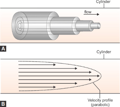
Laminar Flow/Tubular Flow (Figs. 1.2A and B)
Orderly movement of a fluid that complies with a model in which parallel layers have different velocities relative to each other. At relatively low flow velocities, the flow can be modeled on layers or cylinders of flow at differing rates, the fastest velocity occurring in the center of the tube and the slowest at the edge where there is friction between the wall of the tube and the fluid. This distinctive velocity profile is maintained as long as laminar flow exists, that is in the absence of eddies or turbulence.
Hagen-Poiseuille's law: Hagen (in 1839) and Poiseuille (in 1840) described the laws governing laminar flow through a tube. It applies to laminar flow. It states that flow through the tube is directly proportional to the pressure gradient and the 4th power radius and inversely proportional to the length and viscosity of the gas.
Law follows the formula:
Laminar flow 
Where,
r = radius
∆P = pressure gradient
L = length of tube
η = viscosity
Hagen Poisseuille's law is applicable at low flows through flow meters.
Turbulent Flow/Orificial Flow (Fig. 1.3)
Fluid flow which is unpredictable with multiple eddy currents and is not parallel to the sides of the tube through which it is flowing. Turbulent flow is facilitated by corners, 6irregularities and sharp angles. Turbulent flow is affected by the density of the gas. The factors that affect turbulent flow and their interrelation are:

Turbulent flow 
Where, ∆P = Pressure gradient
r = Radius
ρ = Density
Reynold's number: It describes the point at which flow changes from laminar to turbulent, and the spectrum in between the two types of flow. The equation for Reynold's number (Re) is:
Re = ρ w d0/η
Where, Re = Reynold's number
ρ = Density
w = Flow velocity of the liquid
d0 = Orifice diameter
η = Viscosity
The Reynold's number is dimensionless, having no units. For numbers less than 2,000, the flow through a tube tends to be laminar. Between 2,000 to 4,000, the flow pattern is a mix of the two, and above 4,000, the flow is mainly turbulent.
Bernoulli's Principle
Bernoulli's principle is named after the Dutch-Swiss mathematician Daniel Bernoulli who discovered this principle over 300 years ago. In fluid dynamics, Bernoulli's principle states that for an inviscid flow, an increase in the speed of the fluid occurs simultaneously with a decrease in pressure or a decrease in the fluid's potential energy.
Bernoulli's principle is derived from the principle of conservation of energy, which states that in a steady flow, the sum of all forms of mechanical energy in a fluid along a streamline is the same at all points on that streamline. This requires that the sum of kinetic energy and potential energy remain constant. This means that if we alter the energy of one portion of the system, it has an effect on the rest of the system. So, if the kinetic energy rises, the potential energy and pressure must fall.

Bernoulli's equation:
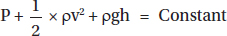
Where, P = Pressure
g = Acceleration due to gravity (m/s2)
h = Height of the tube
ρ = Density of liquid
v2 = Velocity of fluid
Consider a tube with a narrowing as shown in Figure 1.4. There are no leaks, so the volume of fluid at point A is the same at point C. Consequently, the narrowing at point B means that the fluid has to speed up in order to fulfill this continuity. This means that point B has an increase in velocity compared with point A or C, so the pressure falls at this point.
Venturi Effect
The Venturi effect is based on the Bernoulli's principle. The pressure drop induced by the increase in velocity of a fluid passing through a narrow orifice can be used to entrain air or a nebulizer solution.
Venturi tubes are the basis for Venturi injectors which may be used in providing suction or for producing diluted gas mixtures. The venturi tube is shown in Figure 1.5.
The Venturi Mask (Fig. 1.6)—An Application of the Venturi Tube
The venturi oxygen mask is based on the Venturi principle in that relatively rapidly moving oxygen molecules pull along (entrainment) air molecules by two processes:
- The first process is based on the Bernoulli effect in which there is a relative reduction in pressure associated with the higher oxygen velocity.
- The second involves friction between the high-speed oxygen molecules in the lower speed air molecules which has the effect of pulling air molecules into the higher speed stream. Translational momentum transfer occurs as the air molecules increased their velocity.


Entrainment ratio can be calculated as a function of the entrainment flow to the driving (oxygen) flow.
Entrainment ratio = (entrainment flow)/(driving flow)
If the ratio were 8:1 then 8 L/min of air would be entrained by the driving gas (oxygen) of 1 L/min.
Factors that could change the entrainment ratio include transient obstruction, including back pressure, which would ultimately change the oxygen concentration delivered.
Other applications of the Venturi effect:
- Sander's jet injector
- Nebulization chambers
- Modern vaporizers.
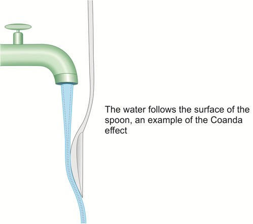
The Coanda effect is an established physical phenomenon of fluid flow. This effect was named after a Romanian aircraft designer Henri Coanda, who discovered the effect after an aircraft he designed went up in flames as a consequence of this effect. A jet stream adheres to the boundary wall and therefore produces a lower pressure along the opposite wall. Essentially any fluid coming into contact with a curved surface will cling to this surface and alter its direction of flow. This can be illustrated by running a thin stream of water from a tap, and bringing the curved surface of a spoon to touch it. The water follows the surface of the spoon (Fig. 1.7). It does so because the solid stationary surface of the spoon slows the layer in immediate contact. This has a drag effect on the other layers, in effect pulling them into the line of the curved surface. The Coanda effect is said to explain the maldistribution of air in the pulmonary tree after a constricted portion of bronchiole, as the flow will stream along one fork of the division, leading to unequal distribution of gas flow and V/Q mismatch.
Applications
- Mucus plug at branching of tracheobronchial tree may cause maldistribution of respiratory gases.
- Unequal flow may result because of atherosclerotic plaques in the vascular tree.
Surface Tension (Laplace's Law)
Surface tension is the result of attraction between molecules across the surface of a liquid either lining a tube or a sphere. The SI unit for surface tension is newton per meter.
The Laplace's law describes the relation between transmural pressure, surface tension and radius. In a tube, the relation between these forces is as follows:

In a vessel wall drop in pressure can lead to instability of these forces and eventually the vessel collapse, which will be detrimental to perfusion.
In a sphere, like alveoli the forces of the Laplace's law is as follows:

As the radius decreases, there would be unrelenting process proceeding to the collapse of the alveoli. This process is arrested by the presence of surfactant in the alveolar lining, which reduces surface tension. As the radius decreases, the relative concentration of surfactant increases, which prevents collapse. In pathological states where the surfactant is inadequate respiratory distress occurs as seen in infant respiratory distress syndrome.
DIFFUSION/OSMOSIS
Diffusion
Diffusion is the process by which there is a movement of solute molecules due to their random thermal motion. It is a passive process, and net movement of the solute occurs along a concentration gradient (from high concentration to low concentration).
The rate of diffusion through a membrane is dependent on the concentration gradient, the area of the membrane exposed, the membrane thickness, and the permeability constant kp.
Q = kpA(C1 – C2)/D
Where:
Q = Rate of diffusion
kp = Permeability constant
A = Area of the membrane exposed
(C1–C2) = Concentration gradient
D = Membrane thickness
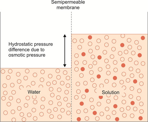
Osmosis
If two aqueous solutions with different concentrations of particles are separated from each other by a semipermeable membrane then water will move across the membrane from the solution with the lower concentration to the solution with the higher concentration. The movement of the water will depend on the difference in the concentration of the particles and the nature of permeability of the membrane. This movement of water is termed osmosis and the pressure which would need to be exerted to halt its movement is called the osmotic pressure. The osmotic pressure is determined by the total number of particles in solution, regardless of molecular nature. The total number of particles will thus depend on the degree of dissociation of solutes (Fig. 1.9).
Osmometry
Osmometry is a technique for measuring the concentration of particles in a solution, i.e. the osmolar concentration. Osmolar concentration can be expressed in two ways:
- Osmolality expressed as mmol/kg of solvent
- Osmolarity expressed as mmol/L of solution.
Osmolality is a thermodynamically more precise expression because solution concentrations expressed on a weight basis are temperature independent while those based on volume will vary with temperature in a manner dependent on the thermal expansion of the solution.
9Based on the total number of solute particles, the plasma osmolarity is 280 to 300 mOsm/L. Ninety nine percent of this is contributed by electrolytes such as sodium, chloride, and bicarbonate. Contribution from plasma protein is small (1 mOsm/L).
If a solute is dissolved in a solvent then the following properties of the solvent change:
- Osmotic pressure increases
- Vapor pressure decreases
- Boiling point increases
- Freezing point decreases.
These are known as colligative properties and are all directly related to the total number of solute particles per mass of solvent, i.e. the osmolality. Theoretically, any of the four colligative properties could be used as a basis for the measurement of osmolality. The most commonly used method in the case of physiological fluids is freezing-point depression.
Tonicity
Although the terms tonicity and osmolality are often used interchangeably, there is a clear distinction. Osmolality is a physical property dependent on the total number of solute particles present in a solution, whereas tonicity is a physiological process dependent upon the selectively permeable characteristics of a membrane. For example, solutes such as urea and ethanol permeate cells freely and therefore will have no effect on tonicity but will increase the measured osmolality.
Colloid Osmotic Pressure
Colloid is a term used to describe solute particles with a molecular weight greater than 30,000. Colloid osmotic pressure, or oncotic pressure, describes an equilibrium pressure measurement when two solutions, one of which contains colloid, are separated by a semipermeable membrane. Interest in its measurement has come from studies in critical care medicine in the prediction of intercompartmental body water movements, in particular as a useful prognostic indicator of pulmonary edema, and of mortality in the critically ill.
HEAT
Heat is a form of energy that passes between two samples owing to the difference in their temperatures. Heat energy tends to pass along a temperature gradient from high to low temperatures. Heating a substance gives its constituent molecules increased kinetic energy. This results in a rise in temperature, or changes its state. Loss of heat results in the reverse process.
Units of Heat Energy
Base SI unit for heat energy is joules (J).
In terms of other SI units:
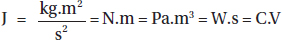
where kg is the kilogram, m is the meter, s is the second, N is the newton, Pa is the pascal, W is the watt, C is the coulomb, and V is the volt.
Calories or kilocalories are also used as units of heat energy. One calorie is defined as the amount of heat reqired to raise the temperature of 1 gram of water by 1°C (1 calorie = 4.186 kJ).
Temperature
Temperature is the property of matter which determines whether the heat energy will flow to or from another object of a different temperature. This is expressed according to a comparative scale. It is that property by which we may quantify the heat energy of a substance.
Temperature Scales
The temperature scale most commonly used tends to be the Celsius scale or the centigrade scale (named after 18th century Swedish astronomer Anders Celsius). It uses the boiling and freezing points of water (100°C and 0°C respectively), at atmospheric pressure.
The Fahrenheit scale (named after 18th century German physicist, Daniel Gabriel Fahrenheit) was set at the lowest freezing point with an ice-water-salt mixture. The freezing point of water is 32°F and the boiling point is 212°F, being 180 degrees apart.
Kelvin temperature scale (named for the British physicist William Thomson, Baron Kelvin) is the base unit of thermodynamic temperature measurement in the International System (SI) of measurement. It is defined as 1/273.16 of the triple point (equilibrium among the solid, liquid and gaseous phases) of pure water. The kelvin (symbol K without the degree sign) is also the fundamental unit of the Kelvin scale, an absolute temperature scale. The Kelvin scale is related to the Celsius scale. The difference between the freezing and boiling points of water is 100 degrees in each, so that the kelvin has the same magnitude as the degree Celsius (Fig. 1.10).

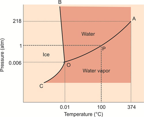
Triple Point of Water (Fig. 1.11)
Water can exist in three phases, as vapor, liquid and ice. These phases depend on temperature and pressure. The transition between water vapor and water is demarcated by the boiling point of water (P), which is 100°C at 1 atm, but which increases with increasing pressure.
Water vapor and water therefore coexist along OA (Fig. 1.11). Similarly, the freezing point of water (0°C at 1 atm) separates water and ice, but decreases with increasing pressure (OB). Finally, OC separates ice and water vapor, and these phases coexist along this line. There is only a single point (O) at which the three phases of water coexist, at a pressure of 0.006 atmospheres and 0.01°C. This is the triple point of water.
The internationally agreed temperature “number” of the triple point of water is 2713.16, because it is the number of units above the recognized absolute zero of temperature, which was deduced from extrapolations of the relationship between pressure, volume and temperature of gases. Hence,the unit of thermodynamic temperature (Kelvin) is the fraction 1/273.16 of the thermodynamic temperature of the triple point of water. The clinical measurement of temperature is described in Chapter 7.
Specific Heat
The specific heat of a substance is the number of calories required to increase the temperature of 1 g of a substance by 1°C. The concept of specific heat is important to the design, operation, and construction of vaporizers as it is applicable in two ways:
- The specific heat value for an inhaled anaesthetic indicates how much heat must be supplied to the liquid to maintain a constant temperature when heat is being lost during vaporization.
- The materials used as a body of vaporizers have a high specific heat to minimize temperature changes associated with vaporization (thermostabilization).
Thermal Conductivity
Thermal conductivity is a measure of the speed with which heat flows through a substance. The higher the thermal conductivity, the better the substance conducts heat. Vaporizers are constructed of metals that have relatively high thermal conductivity, thus maintaining a uniform internal temperature.
HUMIDITY
Humidity is an important aspect of delivering gases to patients in theaters and intensive care. The importance of humidity for anesthetists lies in the comfort of the theater environment, safety with regard to static electricity, adverse effects of dry medical gas supplies, and heat loss from the body. Humidity is a measure of the amount of water vapor in a gas. It can be expressed in a number of ways.
Absolute Humidity
Absolute humidity is defined as actual mass of water vapor present in a known volume of gas, and is expressed as mg/mL or g/m3.
11The absolute humidity of air in the upper airway of humans is about 34 g/m3 and it reaches a peak of 43 g/m3 as it reaches the alveoli.
Relative Humidity
Relative humidity is defined as the ratio of the mass of water vapor in a given volume of gas to the maximum amount of water vapor that the same gas can hold at the same temperature. Relative humidity is expressed as a percentage.
Measurement of Humidity
Hygrometers are instruments that measure humidity; they can measure absolute humidity, relative humidity and the dew point—which is the point at which vapor condenses. They range from simple mechanical hygrometers, through psychrometers (wet and dry bulb hygrometer), to more complex electrical and optical instruments.
Some instruments include:
Hair hygrometer: The length of hair increases with increasing humidity.
Wet and dry hygrometer: It involves utilization of two mercury thermometers, one in ambient temperature and one in contact with water through a wick. The difference in temperature reading reflects the rate of evaporation of water which depends on humidity.
Regnault's hygrometer: Air is blown through a silver tube containing ether. This technique is more accurate than the previous two and gives the relative humidity.
Mass spectrometer: Utilizing the principle of reduction in the ultraviolet light transmitted through the medium containing water vapor.
Humidity transducers: Humidity transducers are used in those places where accurate measurement of humidity is required. They can transform a physical quantity of air humidity into a standard signal which is transferred to a controller. They are normally used in laboratories, ventilation and air-conditioning systems and in any other production process where it is necessary to control air humidity. They have an accuracy of ± 2% over a range of 0 to 100% relative humidity. Humidity transducers generate alarms or turn off a ventilation system when the predefined maximum and minimum values are exceeded.
Humidification
While nose breathing at rest, inspired gases become heated to 36°C and are about 80–90% saturated with water vapor by the time they reach the carina, largely due to heat transfer in the nose. Mouth breathing reduces this to 60–70% relative humidity. This humidification maintains mucosal integrity, ciliary activity, prevents the drying of secretions and helps in easy expulsion of respiratory secretions when coughing. Lack of humidification (e.g. ventilating a patient with dry gas through a tracheal or tracheostomy tube) can result in cracking of mucosa, drying of secretions, keratinization of the tracheobronchial tree, reduction in ciliary activity, atelectasis and infection. Tracheal temperature and humidity fall with increased ventilation, particularly when the inspired gases are cold and dry.
Heat and Water Loss
If totally dry gases were inspired and fully saturated gases exhaled, the total water loss from ventilation at rest would be about 300 mL/day in the average adult. Normally the efficiency of nose, and humidity of inspired air minimize this loss by approximately 150 mL/day. Bypassing the nose with an ETT and not humidifying gases causes maximal losses.
Nonrespiratory water losses are typically 300–600 mL/day but are increased if warm moist surfaces are exposed (i.e. burns, open abdomen), particularly if the operating theater is cold and has high flow air conditioning.
Advantages of Humidification
- Reduced heat loss
- Reduced water loss
- Prevention of ciliary damage and reduced drying of secretions
- Microbial filtration: Some heat and moisture exchanger (HME) filters have viral/bacterial filters.
Disadvantages of Humidification
- Disconnection—some may be bulky and heavy
- Overheating—airway burns
- Overhydration—water intoxication, especially in neonates and infants
- Circuit resistance, dead space and circuit compliance changes—important consideration for neonates
- Infection
- Water clogging—possible particularly in neonates on continuous flow circuits
- Interference with other devices—possibly affects side stream CO2 analyzers
- Cost.
Methods of Humidification
Humidification can be used with any breathing circuit and may be provided for air, oxygen and a mixture of anesthetic gases.
Anesthetic Circuits
- Water's to-and-fro type systems generate warm moist gases but are of historical importance.
- Coaxial breathing circuits (Bain's or Lack's) result in both countercurrent heating of the inspired gases and rebreathing of exhaled gas for some humidification, but they probably only are about 10–20% efficient on IPPV and even less when used for spontaneous breathing (because of the high fresh gas flows required).
- Closed circle circuits warm up after a period of time and do generate water and contribute some.
Heat and Moisture Exchanger and HME Filter
Heat and moisture exchanger filters contain materials such as ceramic fiber, paper, cellulose, fine steel or aluminum fibers in a hygroscopic medium such as calcium chloride or silica gel.
Warm, humidified, expired gas passes through the HME, water vapor condenses within the medium and is then reused for humidification of the inspired gas. The HME is warmed by the latent heat of water condensing on it. This heat is also released during subsequent inspiration. Some filters have bacterial (and/or viral) filtering properties with efficiencies more than 99.9977.
Microbial filtering property may be due to:
Direct interception: For particle more than 1 μm, it is physically prevented from passing through the pores.
Inertial impaction: Particles less than 0.5 μm are held by the filtering medium by Van der Waals electrostatic forces.
Diffusional interception: Particles less than 0.5 μm move freely and randomly (Brownian movement) and subsequently swell up and get filtered by the pores.
Electrostatic attraction: Charged particles are attracted by oppositely charged fibers.
Advantages of HME filters:
- Easy to use in breathing circuits
- Cheap and disposable
- 60–70% relative humidity achieved
- Temperature achieved ranges from 29–34°C
- Can be incorporated as a microbial filter.

Disadvantages of HME filters:
- Need replacing every 24 hours (maximum)
- Secretions can block the filter
- Resistance to flow of gas can be up to 2 cm H2O
- Can add to the weight of the circuit—may be significant in neonates/infants
- Increase circuit dead space.
Water Bath Humidifier
A simple cold-water bath humidifier allows gas to flow through water and carries water vapor as it bubbles out. This type is less efficient as bubbles are large and the loss of heat from the latent heat of vaporization reduces humidity.
The vapor output can be increased by warming the water using electricity (hot water bath humidifier) but must incorporate a thermostat to maintain an operating temperature at about 40°C (Fig. 1.12).
At 37°C, near full saturation can be achieved. A water trap is placed between the humidifier and the patient and is placed below the level of the patient. Vapor output depends on temperature of the water, gas flow and surface area of contact.
The main problems of hot water humidifier are:
- Water spillage into the breathing circuit and even into tracheobronchial tree. A water trap will help reduce this problem.
- Airway burns due to thermostat failure and overheating.
- Colonization of water with harmful bacteria can occur. This may be reduced by heating the water to 60°C.
Nebulizers
Nebulizers produce water vapor in the form of microdroplets (1–20 μcm).

There are three types of nebulizers:
- Gas-driven nebulizer (Fig. 1.13): Gas is passed through a narrow orifice that produces a pressure gradient. This results in water being drawn up through the tube and broken into a fine spray as it comes in contact with the high-speed gas jet. Even smaller droplets can be produced if this spray of gas hits an anvil or a baffle. Most of the droplets are in the range of 2–4 μcm and deposit in the upper airway with a very small amount reaching the smaller bronchioles.
- Spinning disk nebulizer: The rotating disk produces microdroplets when water is drawn onto the disk.
- Ultrasonic nebulizer: Ultrasonic nebulizer has a transducer head immersed in water vibrating at ultrasonic frequency (3 MHz). Ultrasonic nebulizers produce microdroplets less than 2 μcm which are capable of reaching alveoli and are therefore a very efficient form of humidification.
The absolute humidity in different humidifiers is as shown in Table 1.4.
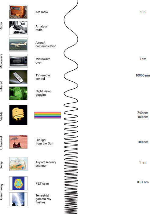
ELECTROMAGNETIC SPECTRUM
The electromagnetic (EM) spectrum is the range of all types of EM radiation. Radiation is energy that travels and spreads out as it goes—the visible light that comes from a lamp in your house and the radio waves that come from a radio station are two types of electromagnetic radiation. The other types of EM radiation that make up the electromagnetic spectrum are microwave, infrared light, ultraviolet light, X-rays and gamma rays (Table 1.5). Infrared light is used in several clinical monitors (infrared analyzers, pulse oximetry, etc.).
|
Beer-Lambert Law
This law represents a combination of two laws, which combine to form a mathematical means of expressing how light is absorbed by matter.
- Beer's law states that the intensity of transmitted light decreases exponentially as concentration of the substance increases.
- Lambert's law states that the intensity of transmitted light decreases exponentially as the distance travelled through the substance increases.
Combining the two laws means that the transmission of light through a substance (the inverse of absorbance) is inversely proportional to its molar concentration and thickness.
Beer-Lambert Law: A = log10 li/lt = εLC
Where, A = Absorbance of light
Ii = Incident light
It = Transmitted light
ε = Extinction coefficient
L = Path length
C = Concentration of absorbing media
Clinical Application in Anesthesia
The Beer-Lambert law is relevant to pulse oximetry (Chapter 7), a monitoring technique that works on the basis of spectrophotometry. The pulse oximeter probe, usually placed on a digit, emits light at different wavelengths The blood absorbs a certain proportion of light, which is dependent on the relative concentrations of deoxyhemoglobin and oxyhemoglobin present.
A photodetector placed at a constant path length away on the opposite side of the probe (and thus digit) senses the amount of light that has been absorbed and processes this electronically to give oxygen saturation and pulse waveform, or plethysmograph.
|
Light
Light is electromagnetic radiation within a certain portion of the electromagnetic spectrum. The word usually refers to visible light, which is visible to the human eye and is responsible for the sense of sight. Visible light is usually defined as having a wavelength in the range of 400 nanometers (nm), or 400 × 10−9 m, to 700 nanometers—between the infrared (with longer wavelengths) and the ultraviolet (with shorter wavelengths). Often, infrared and ultraviolet are also called light. The wavelength (which is related to frequency and energy) of the light determines the perceived color. The edges of the visible light spectrum blend into the ultraviolet and infrared levels of radiation.
Most light that we interact with is in the form of white light, which contains many or all of these wavelength ranges within them. Shining white light through a prism causes the wavelengths to bend at slightly different angles due to optical refraction. The resulting light is, therefore, split across the visible color spectrum. This is what causes a rainbow, with airborne water particles acting as the refractive medium. The order of wavelengths is in order of wavelength, which can be remembered by the mnemonic “ROY G BIV” for Red, Orange, Yellow, Green, Blue, Indigo (the blue/violet border), and Violet (Table 1.6).
Infrared Analyzers
While there is some ambiguity to where the boundaries are for the various “forms” of electromagnetic radiation, the infrared band is typically taken to begin just beyond the red wavelengths of the optical band, around 0.74 micrometers, and extends up to 300 micrometers. When IR radiation passes through a sample, some is absorbed by the sample and some of it passes through (transmitted). The resulting spectrum represents the molecular absorption and transmission, creating a molecular fingerprint of the sample. Like a fingerprint, no two unique molecular structures produce the same infrared spectrum.
Infrared Spectroscopy
Molecules that contain two or more different atom species absorb infrared radiation, because of the nature of the bond between the dissimilar atoms. This property can be used to analyze gases like carbon dioxide, nitrous oxide and all anesthetic vapors, but not oxygen or nitrogen. Asymmetric, polyatomic molecules absorb the light IR radiation at different wavelengths.

Infrared absorption spectrophotometry devices that detect CO2, N2O and inhaled anesthetic agents, are used in the operating room; they measure the unique energy absorbed by the gases and vapors, when a sample of the inspired and expired gas is placed into the optical path of an infrared beam.
These devices have five components (Fig. 1.14):
- Infrared light source
- Gas sampler
- An optical path
- A detection system
- A signal processor.
Carbon dioxide molecules absorb infrared radiation at a wavelength of 4.3 µm. The greater the number of molecules of CO2 present, the more radiation at 4.3 µm that is absorbed. All anesthetic vapors absorb IR radiation at 3.6 µm. Because the amount of infrared radiation absorbed is 16a function of the number of molecules present, it is, therefore, also a function of partial pressure. Thus, infrared analyzers measure partial pressure. Further details of these monitors are explained in Chapter 7.
LASER (SEE CHAPTER 9)
Ultraviolet Light
Ultraviolet (UV) radiation is defined as that portion of the electromagnetic spectrum between X-rays and visible light, i.e. between 40 nm and 400 nm. The UV spectrum is divided into vacuum UV (40–190 nm), far UV (190–220 nm), UVC (220–290 nm), UVB (290–320 nm) and UVA (320–400 nm). The sun is our primary natural source of UV radiation. Artificial sources include tanning booths, black lights, curing lamps, germicidal lamps, mercury vapor lamps, halogen lights, high-intensity discharge lamps, fluorescent and incandescent sources, and some types of lasers (excimer lasers, nitrogen lasers and third harmonic Nd:YAG lasers). Unique hazards apply to the different sources depending on the wavelength range of the emitted UV radiation.
ELECTRICITY
Electricity is broad term for the physical phenomena associated with the “flow” of electrons within imbalanced electrodes, usually from a positive to a negative electrode. Electricity may also be described just as the existence of a “charge” between the subatomic particles—electrons and protons, without necessarily having a “flow”. In the context of anesthesia and intensive care, it is important to understand the concepts of both electrical “charge” as well as “flow” of the electrically charged particles.
Electromagnetism
The electromagnetic force existing within the electrons and protons (and the imbalance existing between them) gives rise to the “electrical charge” of a system. When this charge is transferred to another point or a system, there is a “flow” of electricity resulting in an electrical “current”.
Magnetism is a property of a matter determined by its electronic configuration. When there is zero net orbital motion, the magnetic properties of electrons are nullified mutually, but when the configuration of electrons does not cancel the magnetic properties, the material exhibits “magnetism” and the interaction of these electrically charged subatomic particles gives rise to electromagnetic force.
Electrical Charge and Potential
Electrical charge is a physical property exhibited by the subatomic particles of any matter, causing a “force” created by their electromagnetic interaction. Thus, conventionally, the charge of an electron is –1 and that of a proton is +1. Like charges repel and opposite charges attract. When charge is transferred between points, there exists a difference of the “electrical potentials” between the points that facilitates the transfer. Thus, the “electrical potential” of a point in a conductor is the work done to move a positive charge from infinity to that point.
- A “conductor” is a medium that conducts or facilitates the flow of an electrical current, e.g. copper wire.
- An “insulator” is a material that does not allow the flow of current through it, e.g. glass.
- A “semiconductor” is a material that has conductivity midway between a conductor and an insulator, e.g. diodes, transistors. Current flow through these semiconductors such as silicon chip occurs either by movement of free “electrons” or through free “holes”. Semiconductors are the backbone of modern day electronics; however, the properties of semiconductors may be unique and may not be similar to that of other electrical phenomena commonly described.
Units, Laws and Concepts in Electricity
Electrical charge, flow of current, the difference in the electrical potential between conductors, resistance and the capacitance of the conductors are all inter-related giving rise to the different definitions of the units of measurements in electricity.
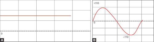
Alternating Current and Direct Current (Figs. 1.15A and B)
- The electrical current when it flows constantly in one direction, this is known as a “direct current” (DC).
- If the current reverses its polarity and alternates its direction of flow cyclically, this is known as “alternating current” (AC).
- Although, in the initial days, DC was predominantly used for all electrical appliances, with the invention of AC, it was actually found to be cost-effective as well as technically advantageous in terms of production and transmission and AC has been adopted throughout the world as the standard current for appliances.
- DC is supplied by batteries including solar cells and flows constantly throughout the cross-section of the conductors such as wires.
- The cycling of AC occurs at the rate of 50 or 60 cycles per second (50 or 60 Hz); the current usually flows toward the periphery of the conductor away from its center.
- AC can be converted to DC by “rectifiers” or adapters, while DC can be converted to AC by “inverters”.

Ampere: The SI unit of measurement of current is “ampere”, which is one of the basic seven units of the “Système International”. One ampere (A) is the amount of transfer of the electric charges (current) passing a point of a conducting system per second. The other units of measurements in electricity are “derived units” and not basic units.
Capacitance
Capacitance in simple terms is the storage of “electrical charge” or energy in a conductor or a set of conductors. When electrical charge is transferred between two conductors, which were not charged earlier, these conductors can then become charged, one positively and another negatively. This results in the establishment of a difference of “electrical potential” between them. Capacitance is calculated as the ratio of the product of the charges of the conductors (numerator) and the potential difference (denominator).
Coulomb: One coulomb (C) of electrical charge is defined as the quantity of charge when a current of one ampere (see below) passes through a conductor within one second (A•s).
Coulomb's law states that charges repel or attract with a force, which is directly proportional to the product of the charges, and inversely proportional to the square of the distance between them.
Capacitor is an electrical device which stores the electrical energy in an electrical field and comprises of two conductors separated by one insulator.
Conductance: Electrical conductance is measured in terms of siemens (S).
Farad: One farad (F) is defined as the capacity of system, when charged with one coulomb of electricity, has a potential difference of one volt.
Impedance and Resistance
Electrical impedance is a concept that extends the property of resistance to alternating currents.
As illustrated in Figure 1.16, current flows from Point A to Point B. The difference in the electrical potential between the two points facilitates the current (I) to flow. Herein, there is introduction of another material (R) that opposes or restricts the flow of current between the two points. This is known as the resistance, which reduces the strength of current reaching Point B. These three parameters are interrelated as defined by Ohm's law.
Resistance is simply applied to DC, since the flow of current is unidirectional. However, since AC changes the polarity in phases, impedance is a property of the conductor which takes the phase of the current also into account along with the magnitude of its resistance. In other words, impedance is a complex calculation of resistance that includes the potential difference, the current flow as well as the current phase. Hence, impedance will be the ratio of potential difference to the current incorporating the frequency domain, which is the characteristic feature of AC.

Ohm: One ohm (Ω) is defined as the resistance between two points of a conductor with a potential difference of one volt, when one ampere of current flows between the points.
Ohm's law: Ohm's law states that the current flow is directly proportional to the potential difference (V) and inversely proportional to the resistance (R). Thus, the relationship between “current” (I), “potential difference” (V) and “resistance” (R) can be expressed as follows:
I α V. and I α 1/R
V = I × R and R = V/I
The exception to Ohm's law is flow in diodes and batteries where the current flow may not necessarily be linearly proportional to the potential difference. The resistance is determined by factors such as the material with which the conductor is made, shape and also other factors such as the cross-sectional area. The inverse of resistance is known as conductance, which is the property of a conductor to facilitate the flow of current.
Resistor is an electrical device that imposes a resistance to the flow of current in a circuit, thereby reducing both the potential difference as well as the strength of the current flow. A resistor is different from capacitor in that it does not store electrical energy and may in fact dissipate energy.
Volt: One volt (V) is the difference in the electrical potential energy between two points of a system, when unit charge is transferred from one point to another.
Watt: Watt is a SI unit for measurement of “power” which is the energy converted or transferred per unit time (Joule/second). In electricity, one watt (W) is the amount of electrical energy transferred when one ampere of current flows between points with a potential difference of one volt.
Wavelength and Amplitude
When a current (AC) progresses in a sinusoidal waveform as shown in Figure 1.17, the distance between two consecutive corresponding points in the wave (red arrows) denote the wavelength (λ). Amplitude is the distance of the highest point of the wave from a zero point (green arrow). Amplitude may also be measured as peak-to-peak (purple arrow), which is the distance between the highest and the lowest points of the wave.
Static Electricity
Static electricity is the property of a system, caused by the discharge of the “electrical charges” of one system to another, when they are not in equilibrium. However, when a current flows from one system to another, there is no net gain or loss to any system.
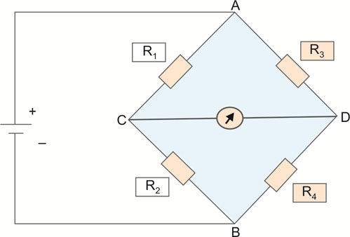
Wheatstone Bridge (Fig. 1.18)
The principle of Wheatstone bridge is used in many clinical measurements and monitoring like invasive pressure, cardiac output, temperature, etc.
- In modern medical equipment, transducers form an important component. Transducer is by definition a device which modifies the signal of one form of energy to another. An arterial pulse is sensed by a diaphragm as a mechanical energy signal, which is converted by 19a transducer to electrical energy and then by a cathode ray oscilloscope to visual signals for this to be displayed in a monitor as a waveform.
- Mechanical energy is usually sensed as “pressure” change by devices known as “strain gauges”, or the “diaphragms”. This pressure change leads to change in the electrical resistance of the system, which is measured by a device such as a Wheatstone bridge.
- Basically, a Wheatstone bridge is a device to measure unknown resistance in a system. It was originally developed to measure and calibrate resistance in equipment such as ammeters and voltmeters. Modern digital equipment may or may not use Wheatstone bridges; however, these are still helpful to measure very small amount of resistance.
- The bridge consists of two series-parallel arrangements of four resistors in a diamond shape (Fig. 1.18). When the resistance of three resistors are known along with the voltage, the resistance of the fourth resistor can be calculated using the following formula:R1 / R3 = R2 / R4 = 1Hence, if R4 is the unknown resistanceR4 = R2 × R3 / R1
Wheatstone bridges are typically applied in transducers that may include strain gauges also known as “piezoresistive sensors”, light-dependent resistors (photoresistive sensors), potentiometers or positional sensors and thermistors, which are resistors measuring temperature.
ULTRASOUND
The ultrasound plays a major role in anesthesia, pain and critical care. The rapidly evolving technology of ultrasound in anesthesia, leads away from the typically “blind” interventions based on anatomical landmarks, done at the risk of their very many variations to the normal. Ultrasound guidance is becoming standard practice, and the future generations of anesthetists need to develop a thorough understanding of this technology and practical skills. It should be part of the core training of every anesthetist.
Basic Physics of Ultrasound (see Chapter 10)
The discovery of piezoelectric effect and its utility in construction of high-frequency mechanical vibrating sources coupled with high-frequency electronic drives provided the basis of ultrasound.
Sound is produced when mechanical energy travels through matter as a wave, producing alternate compression and rarefaction. Ultrasound imaging is based on the scattering of sound energy by interfaces formed of materials of different properties. The amplitude of reflected energy is used to generate ultrasound images. Frequencies used for ultrasound are higher than those in the audible range, and typically vary from 2 to 15 MHz for diagnostic procedures.
Propagation of Sound
Ultrasound transducers work on the principle of piezoelectricity. Within the transducer are arrays of piezoelectric crystals, which have the property of changing shape when an electrical voltage is applied. Application of a voltage enables electrical energy to be converted into sound energy.
Modern systems have arrays that are structured to allow the sound waves generated by one crystal to interact with those from other crystals; consequently, the sound waves can be amplified or diminished.
The sound wave is propagated through the body tissues and interactions occur between the wave and the tissues. If the sound is transmitted through a homogeneous structure, the principal interaction is absorption of the sound. The rate of absorption is least in fluids and greatest in solid structures.
The majority of body tissues are not homogeneous and the sound wave strikes a series of interfaces. At each interface, the wave can be reflected or refracted.
Refraction is usually insignificant. The waves that are reflected back to the transducer strike the piezoelectric crystal. The crystal converts sound into electrical energy. The distance of the reflector can be calculated by calculating the time taken for the sound to travel from and to the transducer. The amplitude of the reflected sound can be used to calculate the reflectivity of the object.
The proportion of sound reflected or transmitted at an interface depends upon the difference in acoustic impedance between the tissues forming the interface. The acoustic impedance is measured in Rayls and is the product of the density of the tissue and the velocity with which it propagates sound. Air and bone have different impedance compared to other tissues; therefore, at such interfaces, the majority of sound is reflected (Table 1.7). Hence, ultrasound cannot be used to image deep to bone or air.
High-frequency transducers produce higher-resolution images but the sound waves are absorbed more as they pass through the body. Low-frequency transducers have greater penetration, but poor resolution.
|
Resolution refers to the ability of the device to differentiate two closely situated objects as distinct structures. Axial resolution is measured along the axis of the ultrasound beam in its direction of propagation. It is directly proportional to the ultrasound frequency. Transverse resolution is measured at 90 degrees to axial resolution. It depends on the width of the pulse beam. Axial resolution is always superior to transverse resolution.
Features of an Ultrasound Image
Recognizing structures on ultrasound takes practice and a good knowledge of the anatomy is a big help. What follows is a brief description of some of the features that make up the image.
Presentation: In almost all applications, the top of the screen represents the probe and as you look further down the screen you are seeing progressively deeper tissues.
Depth: The depth to which you can see is normally shown on a scale running alongside the image. This can be adjusted using the depth adjustor, which will be a prominent control on any scanner. The maximum depth is dependent on the frequency, with lower frequencies penetrating much further, but at the cost of reduced resolution. Hence, lower frequency (2.5 MHz) used in transthoracic echo for visualization of deeper structures. High-frequency probes using frequencies of around 10 MHz, is used in transesophageal echocardiography (TEE).
Typical Appearance of Normal Tissue (Table 1.7):
- Skin appears smooth and bright (echogenic, hyperechoic, highly reflective).
- Fat can be bright or dark (hypoechoic), but subcutaneous fat is typically dark.
- Muscle is also dark, when viewed in cross-section. In long section, sound is reflected back by the muscle fibers and the internal structure of the muscle can be easily seen.
- Fluid, be it blood, effusion or cyst is generally black (anechoic), though thicker fluids such as pus can be bright or dark.
- Tendons are typically bright, but this varies with their orientation relative to the probe.
- Nerves appearance is similar to that of tendons. They are typically identified in relation to the relevant anatomy and vasculature.
- Bone appears as a particularly bright line due to the dramatic difference in acoustic impedance between bone and soft tissue. High-frequency ultrasound does not penetrate bone effectively and therefore the screen is generally black deep to the bone.
Components of Ultrasound Imaging
Transducer
- It converts electrical to mechanical energy and vice versa.
- It serves two functions:
- It converts electrical energy provided by the transmitter into acoustic pulses directed into the patient.
- It receives the reflected echoes.
Receiver and Processor
These detect and amplify the backscattered energy and manipulate the reflected signals for display.
Image Display—Modes
- Earliest A-mode devices displayed the voltage produced across the transducer as a vertical deflection on the face of the oscilloscope. Only the position and strength of a reflecting structure could be recorded.
- M-mode ultrasound displays echo amplitude and shows the position of moving reflectors. It represents movement of structures over time. It is used in the evaluation of cardiac chambers, valves and vessel walls.
- 2D mode or 2-dimensional mode gives a 2D cross-sectional view of the underlying structure and is made up of numerous B mode (brightness mode) scan lines. Commonly used for USG abdomen and Echo.
- Color flow Doppler imaging mode, the velocity and direction of blood flow are depicted in a color map superimposed on a 2D image.
- Continuous wave Doppler mode where a part of the transducer is continuously transmitting and a part is continuously receiving the Doppler signal along a single line that is placed on the 2D image.
Doppler Ultrasound
The Doppler principle is the phenomenon in which sound transmitted from a moving object is perceived by a stationary observer to be of a different frequency depending upon the velocity and direction of travel. Thus, changes in frequency (frequency shift) can be used to calculate velocity of movement of blood.
Uses of Ultrasound in Anesthesia
Regional Anesthesia (see Chapter 10)
Procedures include:
- Peripheral nerve blocks
- Central neuraxial blockade in children and difficult anatomical situations in adults
- Chronic pain procedures: Caudal space injections for low backaches, facet joint injections, lumbar sympathetic blocks, celiac plexus and stellate ganglion blocks are a few procedures utilizing USG guidance.
Advantage of using USG guidance:
- Direct visualization of the neural structures
- Visualization of related structures like blood vessels and tendons
- Guidance of needle under real time visualization
- Avoidance of complications such as intravascular or intraneuronal injection
- Monitor the spread of the local anesthetic
- Allows repositioning of the needle after an initial injection to allow better delivery of local anesthetics to areas which may not be blocked by a single dose.
- Can be used in patients with poor twitch response to nerve stimulation.
Transesophageal Echocardiography
Transesophageal echocardiography is used in anesthesia for the following procedures:
- Assess adequacy of prosthetic valve replacement
- Diagnose ongoing ischemia by detecting fresh regional wall abnormalities
- Assess volume status in patients with hemodynamic instability
- Sensitive tool for early detection of pulmonary embolism
- Transesophageal stress echocardiography to detect coronary artery disease and viability.
Vascular Access
- Central venous cannulation
- Peripheral venous cannulation (obese patients)
- Arterial cannulation.
Advantage of using ultrasound imaging for gaining vascular access:
- Decrease number of “blind” attempts
- Easy identification of variable anatomy
- Avoidance of inadvertent punctures
- Improve overall success rates.
Other Applications of Ultrasound
- Assessment of subglottic diameter to calculate appropriate endotracheal tube size.
- Laryngeal ultrasound to detect patients at risk for postextubation stridor.
- Applied to visualize CSF leak in case of postdural puncture headache, and for application of epidural blood patch under real time depiction.
- Focused assessment with sonography in trauma (FAST): is useful in blunt abdominal trauma, stable penetrating trauma, and assessment of the degree of intraperitoneal free fluid.
- The RUSH Exam—rapid ultrasound for shock and hypotension: This bedside protocol will enable the clinician to assess and effectively treat patients in shock and are critically ill. This protocol consists of:
- To determine the cardiac status:
- Detecting cardiac tamponade
- Left ventricular contractility
- Right ventricular size.
- Effective intravascular volume status:
- Fullness of IVC and internal jugular veins
- Internal bleeding
- Decrease in venous return.
- Assess the major vessels:
- Aortic aneurysm and dissection
- Thromboembolic occlusion.
BIBLIOGRAPHY
- Davis PD, Kenny NCG (Eds). Basic Physics and Measurements in Anaesthesia, 5th edition. Elsevier; London: 1995.
- Edgar L. The physics of fluid flow. [online] Available from http://www.frca.co.uk/article.aspx?articleid=100482. [Accessed August 2015].
- Gilbert-Kawai ET, Wiitenberg MD, eds. Essential Equations for Anaesthesia, 1st edition. Cambrige University Press; Cambridge UK: 2014.
- Hill DW. Physics Applied to Anaesthesia, 2nd edition. Elsevier; London: 2013.
- Jain PN, Ranganthan P. Ultrasound in anaesthesia. Indian J Anaesth. 2007;51(3):176-83.
- Magee P, Tooley M, (Eds). The Physics, Clinical Measurement and Equipment of Anaesthesia Practice for the FRCA, 2nd edition. Oxford University Press; Oxford: 2011.
- Middleton B, Phillips J, Thomas R, Stacey S, (Eds). Physics in Anaesthesi, 1st edition. Scion Publishing; Banbury, UK; 2012.
- Qudaisat Y. Coanda effect as an explanation for unequal ventilation of the lungs in an intubated patient. BJA. 2008; 100(6):859-60.
- Seif D, Perera P, Mailhot T, Riley D, Mandavia D. Bedside Ultrasound in Resuscitation and the Rapid Ultrasound in Shock Protocol. Crit Care Res Pract. 2012;2012:1-4.
- Smith T, Pinnock C, Lin T, (Eds). Fundamentals of Anaesthesia. 3rd edition. Cambridge University Press; Cambridge: 2009.